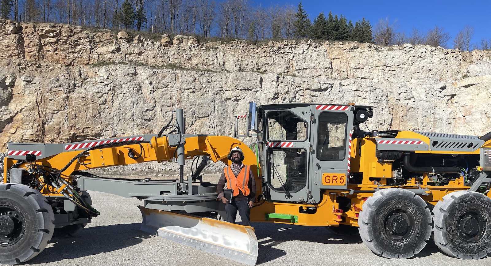

Grader Project
Working at MEDATech Engineering Services I was able to build upon my undergraduate experience in Software and Electrical design and development. I spent most of my time here around nine months developing a Non-certified SIL 2 drive-by-wire diesel-powered grader system.

Responsibilities
As the main Controls Designer, I definitely felt the weight and responsibility of this opportunity and had to rise to the occasion. So, I left no stone unturned. Like many in my position I wanted to know everything there was to this Grader and relied on my experience as well as my superiors advice to guide me through it all.
Research
The research I conducted for this project was extensive in the following areas:
- Engine controller

- Hydrostatic controller
- SIL (Safety Integrity Level) 2 requirements and implementations on fail-safe controllers
- Configuration of I/O modules and peripheral ECU (electronic control unit)
- Client documentation
For both the engine and hydrostatic controllers I read and understood the associated documentation (data sheets and manuals). I would learn specific topics within these manuals concerning functional requirements from the client such as throttle limitation, cold starting, engine and exhaust braking to name a few. Once I was familiar with the content, I would be the lead in meetings with the OEM requesting time with their technical support. I would question their technical support to clear doubts I had as well as informing them on discrepancies in their documentation. During these meetings I would also confirm with the technical team what I knew regarding how to enable certain functionalities through their specific proprietary software. There would also be regular meetings with the client regarding functionalities they wanted to add on.
Cumulating all these resources I would confidently start to configure each controller to their required specification while adhering to safety requirements outlined in the manuals to uphold SIL 2 standards. Adhering to these requirements meant that I needed to communicate with not just one message but a system of primary and redundant messages. This allowed their systems to perform their own fail-safe protocols (request idle engine RPM, limp mode, disable steering, etc) in the event of loss of communications or discrepancies in the information being transmitted/received. These fail-safes are also triggered by checksums, heartbeat counters or internal request. On the master controller where I wrote the main program, I had to also carry on the same SIL 2 requirements. To ensure that I follow the correct requirements and implementation I read and understood CODESYS Safety SIL2 – IEC Programming Guidelines. Through this document I adhered to standards such as:
- EN13849

- EN62061
- IEC61508
- IEC61131-3
Following safety requirements such as:
- Source code reviews
- Use of libraries
- Floating point operations
- Non-naturally-aligned structures
- Multitasking and I/Os
- Multiple mapping of I/Os
- Use of the operators AND_THEN / OR_ELSE
- Calculation of safe outputs
- I/O devices without SAFE data types
- CANopen Safety Stack: cross-communication
That document helped define rules I needed to follow when coding the main program. Even though the clients defined the functional requirements it was our in-house team of engineers that conducted the PHA (Process Hazard Analysis) meetings, following other ISO standards (ISO 15998,13849). In these meetings I contributed little and made it a point to learn as much as I could from the way the senior engineers would simplify problems to bring about safe measures to dangerous outcomes.
| Dangerous Situation | Avoidance Measure | Software Requirements |
|---|---|---|
| Unintended Startup | Vehicle needs to be in neutral, parking brakes need to be applied, operator needs to be in seat and seat belt is worn to enable startup | Dual channel (primary and redundant signals) 1. Joystick transmission modes (N/F/R) 2. Brake pressure sensors 3. Operator seat contact sensor 4. Seat belt sensor |
| Unintended movement (moldboard functions) - no request made by operator, but movement detected | Moldboard valves disabled, feedback sensors, joystick command monitored, operator needs to be in seat | Dual channel 1. Moldboard valves enable button 2. Operator seat contact sensor 3. Feedback sensors 4. Joystick command |
| Intended movement (moldboard functions) - request made by operator, but no movement detected | Moldboard valves enabled, feedback sensors, joystick command monitored, operator needs to be in seat | Dual channel 1. Moldboard valves enable button 2. Operator seat contact sensor 3. Feedback sensors 4. Joystick command |
I also read documentation regarding I/O modules and peripheral ECU’s (electronic control units) to configure them to our purposes for the grader. Communication with the I/O modules were crucial due to having many sensors throughout the grader. This eliminated unnecessary wiring and allowed information to be transmitted through the many CAN networks to be received by the master controller. The documentation for the peripheral ECU’s helped interpreting the values and error codes being sent over the CAN Network. The peripheral ECU’s that I worked with are as follows:
- Wheel angle sensors
- Linear position sensors
- Steering valve
- Articulation valve
- CAN switches

Regarding these ECU’s I needed to configure their source address, baud rate and heartbeat counter interval while adhering to safety requirements like rolling counters, checksums, and primary and redundant messaging. Specifically, to the steering valve I did extensive research into implementing Ackerman steering and the mathematical relationships that need to be maintained regarding the left and right wheel angles.
While configuring all these components I constantly had to refer to client documentation from their internal repository, to find everything from required parameters for the steering and articulation valves (distance between articulation pivot point and front wheel axle, length of the vehicle, etc) to vehicle characteristics like (idle RPM, max required turning radius/angle, etc).
This project reconfirmed my notion that research is crucial to building a safe product. Where I had to rely on my interpersonal skills heavily during this phase of the development. Skills like communication, creativity, adaptability, collaboration, and leadership would be the reasons why I felt like everyone had my back during this whole process.
Concept design / design analysis
Here I wrote and designed the architecture of the software through control/process flow charts, network diagrams and state flow diagrams. I was advised to make the decision to create the master program using as many function blocks through structure text (ST) as I could. This seemed to be the best way forward so that in the event of an issue arising from not complying with any safety requirements, it would be isolated to a minor function block. Additionally, I would use as many SIL 2 certified safety function blocks as I could, as there were already certified. I was responsible for developing the control system for steering, articulation, moldboard functionality, drive, and safe state responses.
Steering Control System
- Closed loop control
- Wheel angle sensor (feedback signal)
- Joystick position (input signal)
- Built relationship between joystick signal and requested wheel position
- Implemented with electrohydraulic steering valve
- Ackerman steering
- Implemented communication between master controller and electrohydraulic steering valve
- Safety checks
- Three individual steering input signals
- If on signal is lost, system can still operate with a set of primary (second) and redundant (third) signals
- Wheel misalignment algorithm
- Interpreted data collected from client regarding left and right wheel position relationship
- Three individual steering input signals
Articulation Control System
- Closed loop control
- Linear position sensors (feedback signal)
- Built relationship between joystick signal and requested angle
- Implemented with electrohydraulic articulation valve
- Linear position sensors (feedback signal)
- Implemented communication between master controller and electrohydraulic articulation valve
Moldboard Control System
- Open loop control
- Joystick button position (input signal)
- Proportional control of solenoid (valve)
- Customizable algorithm from HMI (Human Machine Interface)
- Linear and parabolic characteristics (ability to feather)
- Safety checks
- Directional dual channel feedback sensors (valve)
Drive Control System
- Closed loop control
- Drive pedal (input signal)
- Engine controller - RPM sensor (feedback signal)
- Control algorithm implemented by hydrostatic controller
- Implemented communications between master controller, hydrostatic and engine controller
- Safety checks
- Dual channel drive pedal
Safe State Response Control System
- Monitoring status of all components
- Safety checks
- Standard inputs
- Safe inputs and outputs
- CAN inputs
- CAN communication / heartbeat loss
- Status messages
- Safe states
- Warning state
- HMI warning
- Safety input and output safe state
- HMI warning
- Limp mode
- Safe state steering
- HMI warning
- Steering disabled
- Brakes applied
- Accelerator set to zero
- Safe state articulation
- HMI warning
- Articulation disabled
- Brakes applied
- Accelerator set to zero
- Safe state moldboard
- HMI warning
- Moldboard disabled
- Limp mode
- Warning state
- Recovery
- Cycle Ignition
I heavily relied on the notes I took during the PHA meeting as well as the advice of the senior engineers when creating the safe state response control system. These PHA meetings with the client and team led to discussions regarding what was an appropriate measure to take in the event of a specific fault. Once the code was written at multiple stages there were code reviews with the client’s software team.
Prototype Assembly
Due to covid, the lead times on multiple components were delayed, causing for concern where I felt I might not get the testing time I needed. So once development of the software was completed and I needed to test critical functions, I started creating a test bench with the master controller. I made a request to the clients to send us any components they might have on hand. As the client gave us components such as joysticks, solenoids, electrohydraulic valves, I used the data sheets to know the electrical requirements to add the controller and associated sensors onto the test bench. Once added, I tested proportions of the code related to those components as well as use proprietary software to configure them. On some occasions I would request meetings with specific OEMs to clarify doubts and reconfirm that the parameters I’m uploading to their device according to my rational are valid.
While reverse engineering the joysticks characteristics I realized that the output voltage range of the joystick that I saw using an oscilloscope (unfortunately the datasheet for the joystick wasn’t attainable) couldn’t be interpreted by the safety controller. This was verified through the safety controller’s data sheet. This presented a problem because the client couldn’t order different joysticks that worked with the safety controller. This again was due to long lead times for the item which wasn’t possible within the project timeline. I wanted to give the senior electrical engineer as much information as I could. I presented the data sheet explaining the requirements of the safety controller’s input for a PWM signal and the thresholds it needed to achieve for the controller to interpret it as signal on and off.

Controller requirements (supply voltage 24 (Vb)):
Signal ON
- When greater than (0.7(Vb) = 16.8V)
Signal OFF
- When less than (0.3(Vb) = 7.2V)
Joystick Output (PWM)
- Peak-to-peak voltage = 7.2V
- Avg. voltage = 15.2V
Given this information the senior electrical engineer recommended I use an optocoupler. I did some research into how they work and what it can do for the test bench and found out it works like a MOSFET. I wanted to test if this would work and bought from amazon an optocoupler that represented the type of input/output characteristics I required. Initially, my implementations of the optocoupler didn’t exactly match what I needed. The peak-to-peak voltage was much larger now, but it still didn’t cross below the crucial 7.2V threshold. I therefore looked for some guidance through our Electrical P.Eng for some advice on the issue. I explained the joystick input characteristics going into the optocoupler and explained the basic circuitry of the optocoupler I bought. After some discussion with the P.Eng he made me realize that the optocoupler I bought was incorrectly designed. Knowing the board itself was wrong and my knowledge of how an optocoupler works I started to question which part of this basic board needed some adjusting. I added a smaller resistor to the back of the board and removed the larger one, and it worked. Even though the change was a simple one I learnt a valuable lesson reconfirming that I should always think out of the box. I used this board for my bench testing and later the P.Eng bought an industrial grade optocoupler for the actual grader.
I played a small role regarding the steering axle test bench setup, but I turned it into a learning experience by talking with the hydraulic team regarding the various components they needed to consider when constructing this setup. They first did the crimping of the hoses to the right size and pressure rating. Connecting the axle to the electrohydraulic valve and back to the power pack, which acted as our engine. This supplyed the required pressure for the system so that when I give the command to the valve to open the fluid turns the wheels.
Testing
Once my test bench was completely wired, I began to test and troubleshoot errors as they popped up. The first thing I wanted to confirm was CAN communications between the individual controllers and associated sensors.

Troubleshooting CAN errors
- Termination
- Having each CAN network terminated with a 60 ohm resister
- Tested with a multimeter
- CAN bus load
- Some CAN networks had multiple controllers causing for concern if the busload would be too high
- Tested using CAN software: CANalyzer
- Resolving error messages from controllers and sensors (examples)
- Voltage to low
- Loss of communication
- CAN messsage not received
- Misconfigured CAN messages (PGN)
- Fixed within CODESYS development environment
- Tested using CAN software: CANalyzer, CANmoon or PeakCAN View
- Baud rate issues
- Missing messages on network
- Reconfigured on controllers
- Tested using CAN software: CANalyzer, CANmoon or PeakCAN View
- Heartbeat / Checksum
- Incorrect / Missing
- Fixed bug in software
- Validated through controller error handling system
After getting communications all configured and to some degree, I was able to validate my code, I requested to the client that I was ready to test the remainder of my code. They allowed me to come by to their manufacturing site and I was surprised to see the Grader was still being built. I quickly introduced myself to everyone and got to work. Since this was a new setup that was still in the purpose of being built. I had to do all the testing in regarding to the CAN communications again. I connected to the master controller and right away saw communication errors.
At this point because I was at the clients manufacturing site, I didn’t have much control over the Grader other than connecting to the master controller. It was at this point that I relied on my superior’s experience on what I should do because I was clearly feeling inexperienced. When the senior engineer came to the client site, I was amazed how he communicated with everyone and how he not only knew systems like the Grader but showed confidence in his directives to the mechanical team. Whether he was wrong or right didn’t matter they all followed what he had to say to figure out why communications were down. With his help we found out the wiring harness that was connected from the master controller to the Grader system was faulty and had to be replaced. Even though this was progress in that one day just by shadowing his every move I gained unmeasurable experience. I now knew what was expected of me as the solo controls designer for this project and how I need to take charge of any situation that has anything thing to do with software. The senior engineer left that day with me confidently telling him that with what he has showed me I can carry on.
After that day I felt that this project was truly mine and if the Grader was going to be an excellent product it would only be possible if I made it so. With a new harness connecting the master controller to the other controllers and associated sensors, I recontinued my CAN communications tests and made sure that if there was an error, I would communicate it accordingly to the mechanical team and resolve the issue. As the first week passed, I felt like I was a part of the team and I’m sure the mechanical team felt the same way. We all had the same goal and that was to get this baby rolling. Seeing how I communicated with the mechanical team the hydraulic and electrical team felt comfortable communicating their issues directly to me as well as helping us with our issues. Seeing our progress, the vice president of engineering wanted me to directly give him updates as he knew I had a clear understanding of where we were in the build process. I used this opportunity to learn from his experience as well because the situation wasn’t looking so good for us, the deadline was approaching around the corner and the Grader wasn’t even fully built yet, let alone fully testing my software. Due to the situation, I knew I needed to step up and requested that I be able to work long hours to support the mechanical team that worked in shifts. Now that I worked long hours and was a part of the whole process, once a system was built, I would use my software interface to check if the wiring was all done correctly before we tested the system.
While reading through the documentation and creating the software I planned to test certain functionality and learnt some other criteria from the operators that rode the Grader.
Functional Checks
- High lift float
- Proportional gains tuned
- High lift
- Circle turn
- Blade slide
- Blade tilt
- Drag link
- Steer (front)
- Steer (articulation)
- Accelerator
Safety Checks (safe state)
- Steering faults
- Braking faults
- Drive system faults
Other Checks
- Drive motor speeds adjust when articulation operated
- Drive system responds properly to a sudden change from FWD to REV and vice versa
- Hydraulic oil temperature
- Fans
Start Up Tests
- Engine start
- Pump pressure
- Open loop
- Closed loop
- Charge valve
- Throttle response
- Park brake release
- FWD / REV direction
- Service brakes
Mobile Tests
- 1st/2nd/3rd gear
- Speeds
- Acceleration
- Coast to stop
- Stopping distance
- Turn radius
- Brake test switch
Out of the many learning opportunities, one that stood out to me during this time was management/organization and the crucial role they play in any project. During a moment when I was overwhelmed with client requests, I extended a hand to my superiors for some guidance, and they taught me some tool they used in similar circumstances that helped me instantly as I implemented it. This reconfirmed my belief that there is still so much for me to learn and that I should always utilize my resources to their fullest extent.