
Dean’s Choice Awarded Capstone Project

In addition to my practice in nuclear research, I also have experience in Software design and development. These skills were honed throughout my final year capstone project, in which I was one part of the 5 student team in developing and manufacturing an automated motion tracking and response system for advanced soccer training.
The goal of this device was to be an accurate, portable, versatile and an accessible means of soccer training for a variety of skill levels. S.T.A.R.S. is an automated ball launching machine capable of tracking a player while pivoting. Coupled with the launcher are four small net-like targets that can detect if a ball passes through the target. From the launcher and target tracking systems, information about how well passing drills are performed (pass speed, pass timing, etc.), will be collected. The system has the added functionality of being able to anticipate player movements and launch a ball to where they are predicted to be, specifically target areas of the body (feet, chest, head). S.T.A.R.S. selectively passes to those areas, which is controllable via voice commands remotely or through a touch screen on the ball launcher. S.T.A.R.S is split up into 9 modules, which are stereoscopic vision, laser range finder, pitch and yaw motor control, launcher motor control, wireless communication, voice control/wearable device, player targets, graphical user interface and central control system.
Module 1 Stereoscopic
The stereoscopic vision system utilizes two cameras housed on the body of the launcher that provides the system with a large field of view. The tracking system is able to recognize a player and determine the distance in the X and Y planes from the launcher to the player within 0.5 seconds using a colour tracking algorithm. For this to work, the player is required to wear a jersey of a specfic colour. This data is used to rotate and aim the launcher toward the player and adjust the speed of launcher the motors to deliver the ball to the target player with a high degree of accuracy.
Using two cameras, it is easy to calculate the distance of an object without knowing its size. This can be done knowing the focal length of the camera, baseline seperation between the cameras, pixel size of the camera and the disparity value (the difference in pixel position for an object appearing in either camera). As the focal length and pixel size are inherent camera properties and the baseline separation should not change while the camera are in operation, the distance is directly and inversely related to the disparity between the cameras. When disparity is minimized, this correlates to a higher distance, and vice versa.
The higher the pixel resolution of the cameras used, the greater the range of possible disparity values. This results in a higher accuracy and range of distances that can measured. In recognition of the dependency between disparity and pixel size, this relationship was taken into account when considering available camera options. 8 megapixel cameras compatible with the Raspberry Pi were therefore acquired for the purposes of implementing stereo vision.
Normally, a Raspberry Pi only has one ribbon cable slot available to accept a camera module. To work around this limitation, one must either use a proprietary Raspberry Pi board that has multiple camera ports or use multiple Raspberry Pi’s with one camera connected to each Pi. The latter strategy was eventually adopted for the purposes of implementation, due to its perceived simplicity over other possible options. Given the focal length of both cameras and the baseline separation between them, the disparity can be determined from an object’s shift in position between the two cameras and having the Pi’s communicate this information with each other.
Detecting and tracking objects via their colour can be an effective and efficient method for allowing the stereoscopic system to determine a specified target is away from the cameras. If the specific colour values of the target in terms of the colour space used are known to a reasonable degree of certainty, a range of values can be set such that the colour detection algorithm will look for objects or spots in the image that are within that range of set values. In consideration of these values, a mask generated from an input image will have regions that comply with these parameters appear as white, while regions that are outside the specified range will appear as black.
![]() Choosing an appropriate jersey colour and subsequently tuning the HSV values to reflect that colour most accurately will in turn maximise the accuracy of the stereoscopics system, limiting the number of false detections captured by the masking process described above. Additional steps such as Gaussian blurring, erosion, and dilation were also implemented into the algorithm to limit the amount of high-frequency in the mask that may lead to false positives.
Choosing an appropriate jersey colour and subsequently tuning the HSV values to reflect that colour most accurately will in turn maximise the accuracy of the stereoscopics system, limiting the number of false detections captured by the masking process described above. Additional steps such as Gaussian blurring, erosion, and dilation were also implemented into the algorithm to limit the amount of high-frequency in the mask that may lead to false positives.
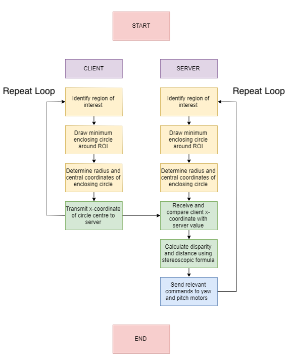
The method responsible for monitoring and controlling the stereoscopics currently has each camera identify the largest region of a specific colour present in its field of view, draw a minimum enclosing circle around the region of interest, and then determine using the centre coordinates of the circle the disparity between the two cameras. Using the disparity calculated in this fashion, the distance is them determined. Choosing an appropriate distance to place the cameras apart was influenced by the space available on the platform, the desire to improve the accuracy of the stereoscopics at long distances, and how much of a blind spot right in front of the cameras is allowable. If all other variables are kept constant, increasing the baseline separation increases the possible range of distances that the stereoscopics can track over. This comes at the expense of creating a blind spot right in front of the two cameras. However, as the launcher should never need to deliver a ball right in front of itself, this was deemed an acceptable tradeoff.
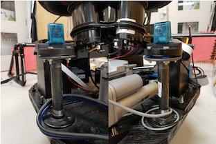
To mitigate any possible damage to the cameras, the modules are placed in cases and then mounted using a custom setup. The setup reduces the effects of vibrartions on the cameras using 3D-printed mounting structures and rubber bushings. Any unchecked vibrations can cause the disparity to deviate between the cameras, which can cascade into the system returning inaccurate distance measurements. Mitigating the effects of these vibrations will ensure that the user can have a high degree of confidence in the accuracy of the calculated distance.
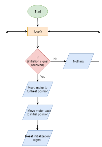
In essence, the operator of this setup can be expressed as shown in the flowchart below. The region of interest is determined by program looking for any contours that match the HSV colour space specifications of the colour in question. Data is transmitted from the client Raspberry Pi to the server Raspberry Pi using an Ethernet connection. The TCP/IP protocol used by the Ethernet ports is proven to be robust, reliable, and fast, which makes it a good choice for real-time communication and data transmission. This speed is necessary for ensuring the most accurate distance measurements are then passed onto be used by other modules on the launcher, and mitigates the difference in processing speed that may arise between the server and client.
Module 2 Laser Range Finder
In addition to the stereoscopic vision system, a Laser Range Finder (LRF) will be used for a more precise distance measurement, making use of an optical time-of-flight (TOF) modality. This allows for the sensor to only be located on the launcher, without necessitating a receiver on the player. Having redundant distance sensors, especially ones that are each optimal at a certain range, allows for sensor fusion to select the most reliable readings.
A laser range finder emits a pulse of laser at a target. The pulse then reflects off the target and back to the sending device.This TOF principle is based on the fact that laser light travels at a fairly constant speed through the Earth’s atmosphere. The formula for distance is also very straightforward: D = ½ (speed x time).
Initial considerations were to utilize a cheaper and also simpler TOF method as an attempt to innovate a relatively stagnant technology, however the optical TOF distance sensor is a much more capable and robust solution to this problem. The operating frequencies of the optical sensor (GHz) to achieve a more reliable result than the ultrasonic TOF sensors could achieve. Given the complexity of the high frequency circuitry, these sensors are impractical to engineer within the given time frame at the time, thus the two devices were chosen for testing. Interfacing to the device is done via a custom programmable microcontroller that provides serial output, which will be used to obtain the range via a Python function.
Testing of the first device to detect a person in outdoor and indoor conditions showed accurate results between 0-15 meters, but had a difficult time detecting the player beyond this. Tests performed by directing the sensor at a wall or large surface produced more reliable results between 15-30 meters. In practice the maximum range of the device is 30 meters dependent on ambient lighting, while the range for a small target (person ~45 cm wide, 180 cm tall) drops off around 15 meters, due to reduced reflectance of the target.
The second device provided a more reliable result to as much as 25 meters (dependant on the ambient lighting/interference), however the lower FOV will restrict its usability at these ranges due to resolution of the Yaw positioning motor depending on the gear ratio and programming.
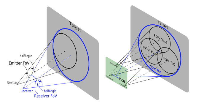
The basic theory of the optical TOF sensor is quite similar to that of traditional ultrasonic sensors, the main difference of course being the speed of the wave (C_air). A major challenge in the manufacture of such sensors is the alignment of the optical axis and spacing on the PCB as a result of manufacturing tolerances. As a result, the receiving photodiode must have a greater FOV (field of view) than the transmitter, since the FOV has a great impact on the amount of ambient light and signal collection, there is a clear tradeoff between FOV and performance. The devive we choose is an example of a multi-zone arrangement, an attempt to improve performance while maintaining FOV, uses multiple transmitting LED’s.The second device uses a diode laser (Class 1: CE Certified), giving it a much more narrow FOV, both devices use infrared light at ~950 nm.
Due to the extreme directional properties of the above LIDAR devices, the most effective solution was found to be a combination of the two sensors mounted on the front of the launcher. This effectively decreases the directionality of the LIDAR measurements and increases the probability that the beam will fall on the target. In order to determine the devices suitability to this project they must be capable of detecting the player given the resolution of the Yaw motor control.
Module 3 Pitch & Yaw
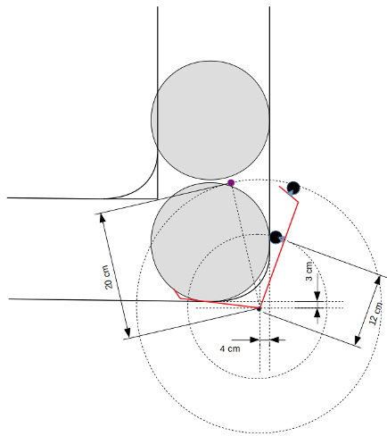
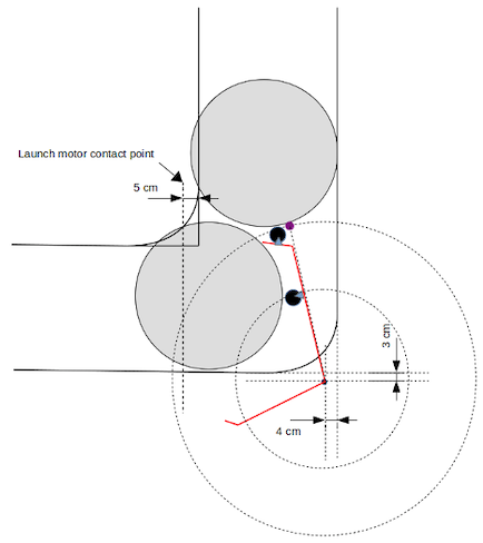
The purpose of the pitch and yaw motor control is to set up the initial conditions for the trajectory of the launcher motor control and also be capable of following the soccer player. In this set up to account for the players top speed, we’ll be using the record speed of 44 km per hour, obtained by Usain Bolt. This speed will account for the most strain being placed on the pitch and yaw motor controls. As this will require the yaw motor controls to move the fastest to be able to track and follow the player 7 m in front of the launcher running perpendicular to it. To calculate the time elapsed following Usain Bolt, the diagram below is used to get the total distance he covers.
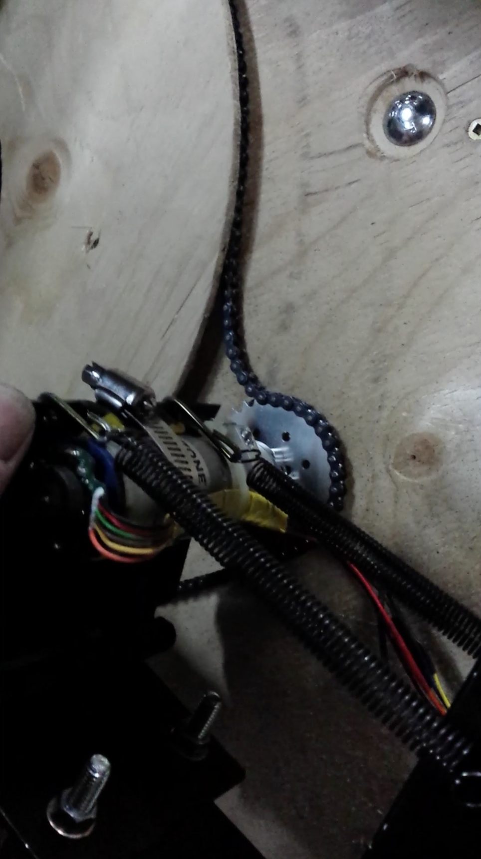
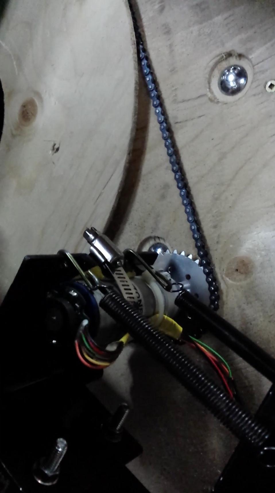
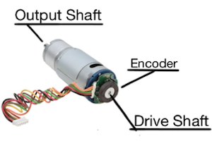
Based of the mathematical modelling the yaw motor that was selected is a planetary gear motor with a built-in rotary encoder. This motor is capable of reaching torques of about 5000 oz-in, which is magnitudes above the required maximum torque. The secondary reason this motor was chosen was because of the built-in rotary encoder fixed onto the drive shaft of the motor. A rotary encoder is capable of reading the angular position and movement of the drive shaft and converts this into a digital signal that can be decoded within the Arduino. The rotary encoder that is attached to this motor is a relative encoder. This means that the encoder conveys the angular position and movement only from the initial position the drive shaft was in. The type of sensor the encoder is using is a magnetic hall effect sensor. As the drive shaft rotates the magnetic field sensed by the sensor repeatedly returns a digital high signal. Once the magnetic field is no longer sensed, the encoder returns a digital low. The process of the signal changing from low to high and back to low is considered as two countable events. Since accuracy is a major component in the yaw motor control, the third reason this motor was chosen was for it’s planetary gearbox. The gear ratio is 368.783:1. To understand the advantage that comes with this gear ratio, the rotary encoder needs to be examined in a bit more detail.
There are 12 magnetic segments in the wheel connected to the drive shaft and two channels that output a digital signal when a magnetic field is present. Since there are 12 magnetic segments in the wheel and two channels to record the passing of the magnetic field, the rotary encoder has 48 countable events per revolution (every 7.5˚ there will be an event) at the drive shaft. The planetary gearbox plays a strong role here as it effectively increases the accuracy. Since the gear ratio is 368.783:1, the rotary encoder will read 17,700.624 countable events per revolution (every ~0.02˚ there will be an event) at the output shaft.
The encoder library utilizes the interrupt pins on the Arduino Uno allowing the program to read the encoder properly without missing any countable events. This was done by connecting both the encoder channel leads to the interrupt pins 2 and 3. At this point we were able to create an equation that let the program know how many countable events needed to be read to rotate one degree. Since there are 17,700.624 countable events per revolution, for one degree there are 49.1684 countable events. A gear ratio needed to be included in the equation. This ratio was found by measuring the displacement caused by the rotating platform for a given angle at the yaw motor.
Now that the encoder is reading all countable events, we’re able to constrain the movement of the launcher, having its starting position set to 0˚ and capable of turning 80˚ in either direction (80˚, -80˚). The movement of the launcher is constrained to this range of motion for two purposes: first, as a safety concern, so as not to allow the launcher to be able to launch the ball in any direction and second, the combined 160˚ of rotation is sufficient to ensure the player is positioned in the centre of the FOV at all times.
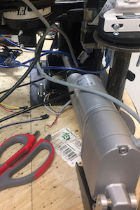
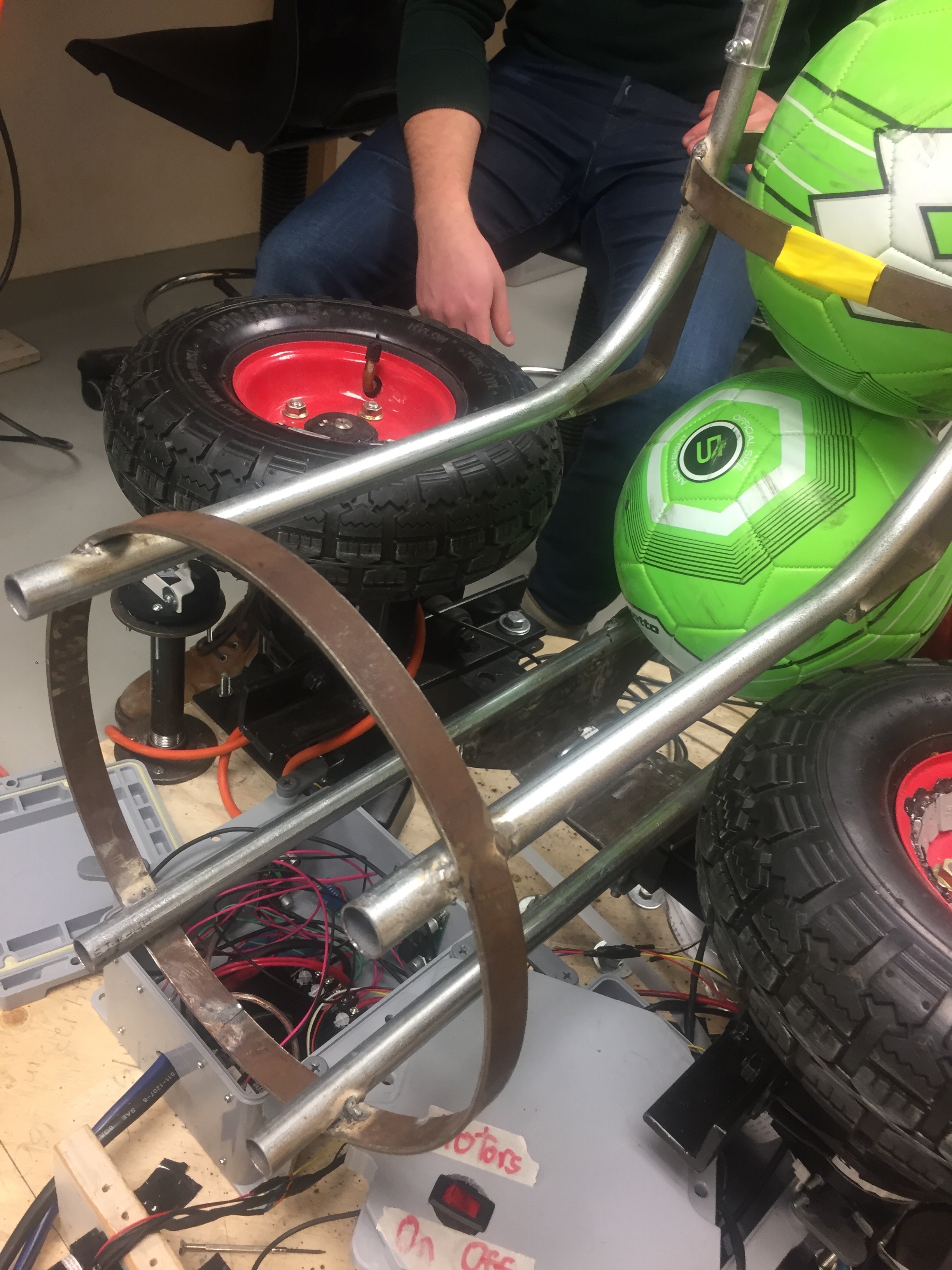
For this reason, a reset function was implemented. The reset function allows the launcher to rotate back to the starting position recognised as 0˚. By rotating the launcher to the start position the launcher can be moved more carefully, due to the weight being distributed evenly with regards to the chassis. At this stage of the construction, the stereoscopics have also been added to the launcher platform and is connected to the yaw motor control seen in the picture below.
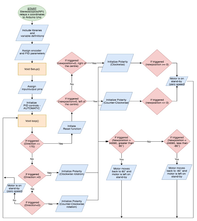
What occurs between the stereoscopics program and the yaw motor control program can be described in essentially 3 IF statements. The stereoscopics program locks onto the target coloured jersey acquiring the x coordinates seen from both the Raspberry Pi camera’s. The x coordinates used to calculate the disparity, are the same values used to control the yaw motor control program. The information is gathered on the Raspberry Pi’s and then transmitted to the Arduino Uno through serial communication (USB).
- If the jersey is seen to the left of the launcher the yaw motor control program will rotate the platform to the left to center itself with the jersey.
- If the jersey is seen to the right of the launcher the yaw motor control program will rotate the platform to the right to center itself with the jersey.
- Lastly, if the jersey is seen to be centred in front of the launcher the yaw motor control program will be on stand-by, as the player is already centre for optimal readings of the distance.
This is a continuous feedback process between the stereoscopics and yaw motor control program. Examining the serial communication between the two systems, it can be seen that on the stereoscopics side it is constantly outputting to the yaw motor control program the PWM signal that turns the platform. As the player is approaching the centre of the FOV, the PID control changes the PWM signal to also approach zero. This way the farther away the player is to the center of the FOV the faster the platform will rotate. Depending on the above mentioned IF statements, the direction will be dictated.
PID control has also been implemented onto the yaw motor control program through a PID Python library (see the Ball Launching Mechanism section for a discussion on PID control). Minimizing all sources of vibration is a must regarding the stereoscopics as this is the central unit that relays the position of the player to the yaw and pitch motor controls. Incorporating the PID library into the yaw motor control program allows for the platform to rotate more smoothly with minimal overshoot and help reduce abrupt movements, effectively reducing the amount of vibration created as well as reducing the stress on the motor.
The pitch motor that was selected is a 4” stroke 115 lb thrust heavy duty linear actuator. The mass that was assumed for the platform was 30 kg (66.14 lb). Even though this mass is distributed unevenly across the platform the linear actuator was selected to be able to handle the full weight of the platform. Another consideration for this selection was the built-in potentiometer that controls the position of the linear actuator. The potentiometer is rated to 10 kΩ moving one inch every 2.5 kΩ [22]. The potentiometer leads output an analog signal that ranges from 43 to 973 describing the number of steps countable between 0 to 4 inches. Unlike the yaw motor the pitch motor is very sensitive to the placement, relative to the pivot point where the launcher motors are connected to. Since the linear actuator has a stroke of 4 inches, the linear actuator needs to be 4 inches away from the pivot point. This will allow the pitch to be able to move from 0˚ to 45˚.
Measurements of the linear actuator made by the potentiometer are not absolute, but instead are relative to the last recorded position. Alternatively, the linear actuator encoder has been used to measure the pitch angle consistently. To increase the accuracy of these measurements, an accelerometer has been mounted on the launcher platform in order to measure the difference between the platform and the horizontal plane. This allows the launcher to detect when not on flat terrain, such as a bumpy field, and accommodate the pitch angle such that it remains measured with respect to the true horizontal. Further, PID control has been implemented within the code for the pitch, allowing for smoother movement of the linear actuator. An explanation of the PID function may be found in the Ball Launching Mechanism section.
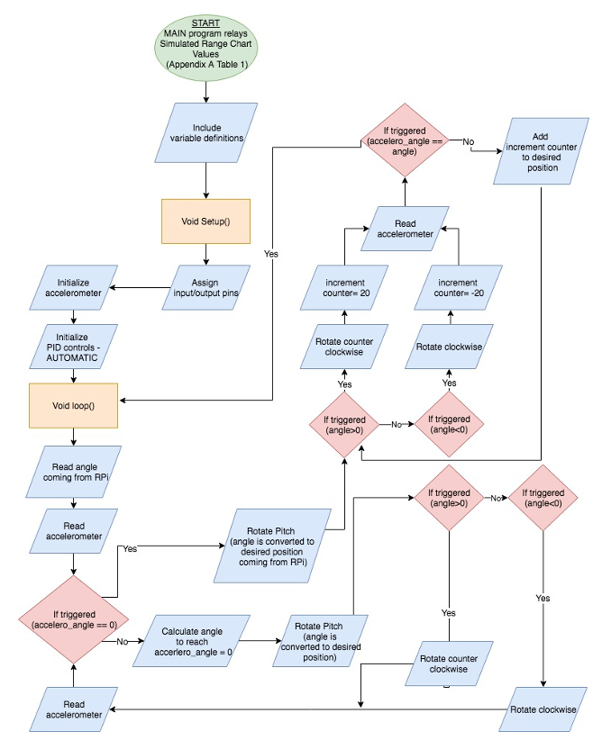
Bringing the focus back to the program flow, once the distance to the player is obtained, the Raspberry Pi will continue to run the MAIN program where it will pull up the values from a Table to figure out what pitch angle is required. This specific value will then be written to the Arduino Uno. Once the Arduino has received this value, the program will first check if the launcher is on level ground. If the accelerometer attached to the pitch motor control sends a signal that does not say its on level ground the program first corrects this. This is done first in order to minimize errors on the launcher shots from one shot to the next. Once the pitch motor control is level the angle received is then checked whether the angle is positive or negative. This will distinguish which direction the pitch motor control needs to travel. Once the angle is read, the accelerometer is read by the pitch motor control program and referenced to see if the angle given by the Raspberry Pi is the same as the readings from the accelerometer. If the readings don’t match, the desired position is incremented 20 steps in either direction depending on where the desired angle is, with reference to where it is currently. Once the desired position is reached the program again awaits for the Raspberry Pi to relay a new angle. The flowchart below will assist in the understanding the code.
Module 4 Ball Launcher
The ball launching system consists of a hopper that is capable of storing five balls that feed into the launching mechanism, which is itself comprised of two motors rotating in opposite directions mounted on either side of a rail to guide the balls. Varying the rotational speed of the launcher motors will modify the speed at which the ball leaves the launcher, and by extension the distance it is able to travel. The central program of the device will determine an appropriate launching speed based on the distance that the player is from the launcher, where on the target (head, chest, feet) the ball is set to be aimed, and the level of speed at which the ball should be travelling when it reaches the player. For stationary targets and moving target, the launcher is be able to launch the ball within a range of 5 to 25 meters.
The general design of the ball launcher utilizes a dual flywheel configuration. The key factor for pursuing this design, with the flywheels oriented horizontally, as opposed to vertically or at some offset angle, was the fact that the device ideally would be able to create curved shots, similar to those achieved by actual players. This curve is achieved by having a difference in the wheels speeds relative to each other in order to generate spin on the ball. This spin causes the ball trajectory to curve in one direction or the other depending on the motion of the spin. Having the flywheels oriented horizontally is the only way to generate this curve consistently. Having the flywheels oriented vertically would allow for adding topspin or backspin to the ball. For the overall functionality of this device however, it was thought that the ability to curve the ball was more desirable than generating topspin or backspin.
Additionally, this configuration is used by many commercial ball launching systems and research into a number of alternatives for the launching mechanism and the relatively large distance requirements of our device indicated that this mechanism was likely the best option to pursue in terms of performance, available supplemental mechanism information, and cost.
Based on the mathematical modeling, motors were sourced that had the ability to provide substantially more torque and speed than was required to ensure that the required distance specs could be met with a healthy margin for error when accounting for various losses, while still being generally affordable.
The motors needed to be controlled individually. This enables curve to be generated on the ball by varying the relative speeds of each motor, and also helps account for the fact that DC brushed motors often don’t spin as fast in one direction as the other at a given voltage, and the motors will be spinning in opposite directions to one another. A commercial motor driver module was used that has a number of other features such as thermal protection to prevent overheating and current limit protection to prevent damage, that improve its reliability.
PID Implementation
PID methods are widely used forms of control systems where continuous control is required. Essentially, a PID controller is continuously fed data on a process variable which it compares to a setpoint or desired value for that variable. The difference between the setpoint and process variable value is then calculated and known as the error term. The control system then applies corrections to the system using this error term and proportional, integral, and derivative correction factors.
The PID control function can be expressed as follows:
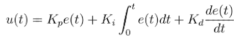
The coefficients Kp, Ki, and Kd are for the proportional, integral, and derivative factors, respectively. Kp is the proportional coefficient and works to correct for current error values, simply multiplying the error term by some constant value, leading to large outputs when the error is large and small output when the error term is small. Ki is the integral coefficient and works to correct for past accumulation of errors, helping to eliminate residual errors that may accumulate over time. Finally, the Kd term is used to estimate and correct for future errors in the system by accounting for the rate of change of the error term in the system.
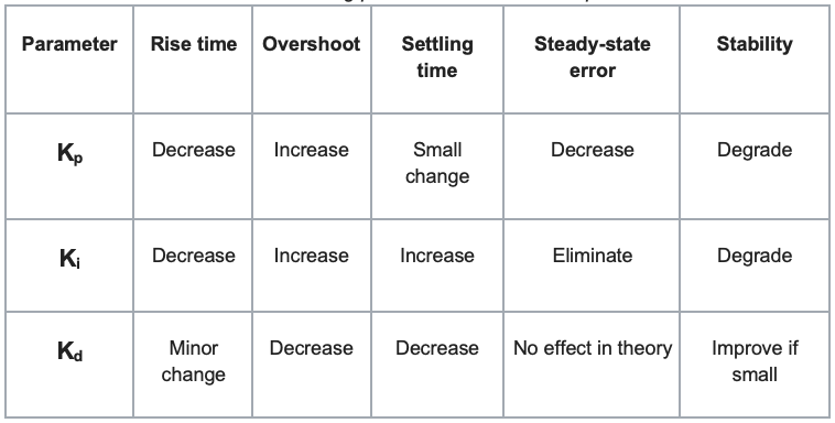
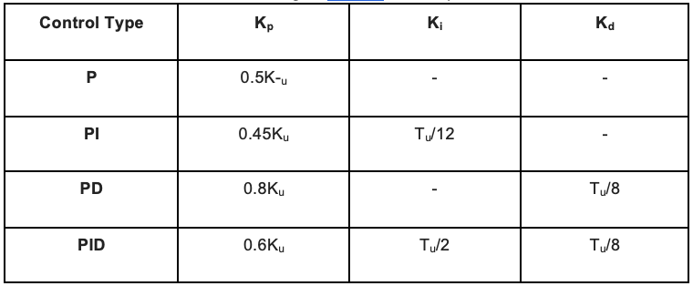
The effects of the three process coefficients are summarized in the table below:
This control function variable u(t) is then fed back into the system and is used by some device which can affect the state of the system, such as a motor or actuator. The value of the u(t) term affects the extent to which the control device affects the system, allowing for correction of the system to reach the setpoint. These coefficients can then be tuned, with different values being optimal for different systems due to the nature of the systems and their responses, with the goal being a system response that is essentially critically damped, quickly approaching the setpoint without overshooting or oscillating around that point.
One method of tuning, and the one that serves as the basis of tuning in this project, is the Zeigler-Nichols method. It is a general guideline that can often be used to get good results for a PID control system. The general methodology for this tuning process involves increasing Kp until stable oscillations are present. This value of Kp is the then noted as the ultimate gain, Ku. Tu is the period of oscillation when the ultimate gain is used. The Ki and Kd terms can then be included based on the values of Ku and Tu in order to reduce oscillations and overshoot, generally resulting in reasonably good control parameters. Specific values for the Ziegler-Nichols method are shown in the table below:
The PID process only relies on knowledge of the process variable being monitored and thus can be quite versatile. This is because it requires no knowledge of various factors that may affect the process variable, allowing for very complex processes to be controlled through PID mechanisms.
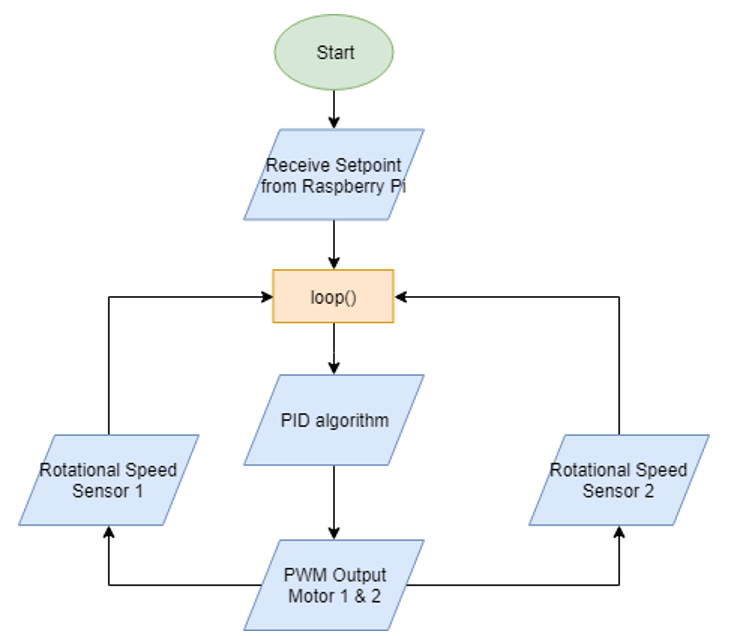
In order to use a PID feedback system for controlling the motor speed, it is necessary to have some sort of device to measure the actual speed of the motors. Therefore, attached to the shaft of each motor is a rotary encoder to give precise feedback on the speed of each motor, since just the voltage may not be perfectly indicative of the actual rotational speed. The encoder consists of an acrylic wheel mounted to the shaft with one hole drilled near the edge. A photo interrupter module (consists of an IR LED and receiver) is mounted near the edge of the acrylic disk, and every time the hole in the disk passes through the photointerrupter, a pulse is generated that signals an interrupt on the Arduino which then records the time of the pin transition. By keeping track of the time between subsequent pulses, the motor speed can be determined.
The Arduino then reads the speed feedback from the encoders and using a PID control system, compares the actual RPM against the user input RPM, and makes the required corrections to the PWM signal controlling the motor speed until the actual and desired speeds are more or less equivalent.
Module 5 Wireless Comunication
Wireless communication for this system is required to communicate data from the player to the launcher, and from the targets to the launcher. Wireless communication in this project is handled by a collection of modules, a type of 2.4 GHz wireless transceiver capable of interfacing with an arduino. The wifi module can be connected to the Arduino using the supply voltage, ground and two supporting pins for Tx/Rx communication.
The wireless module was chosen due to its affordability, extensive catalogue of operating resources, and large maximum operating range of 100 metres (in ideal conditions). It is capable of communicating consistently and with a high success rate via serial communication. Being the principal means of communication between the player and the launcher.
The modules used for the wireless communication can be configured as either a transmitter or receiver and can be switched back and forth as necessary. They cannot both receive and transmit data at the same time though, so the configuration for the system needed to be carefully considered, in order to avoid potential timing issues that would arise when trying to have the devices switch roles and then determine time frames for them to be listening/transmitting. To avoid this, the system was designed so that the central launcher module always acts as the master/transmitter, and then there are five slaves/receivers for the 4 targets and the player.
This is possible because the module has a useful feature where the receiver can pre-buffer information that is automatically sent back to the transmitter when a signal is received, through an automatic acknowledge function. As soon as the receiver receives any data from the master, it automatically sends back a predetermined value to the master without ever having to switch roles.
The system is then broken down into three sections:
Launcher (Master)
- Always a transmitter
- Will send an initialization signal (an integer from 1-5 representing a difficulty value) to the designated target to initialize that target
- After initialization, the master then periodically polls the target to see if the ball has gone through the target to get the ball speed; the master polls the slaves every 10 ms
- Also polls the player to see if it receives an integer representing a designated voice command
Target (Slaves)
- Always a receiver
- Waits for a signal of the ball being detected, and it then buffers a float representing the ball speed to be sent back to the launcher when prompted
Player (Slave)
- Always a receiver
- Waits for a voice control signal from the player and if detected, it buffers an integer representing that command to be sent back to the launcher when prompted
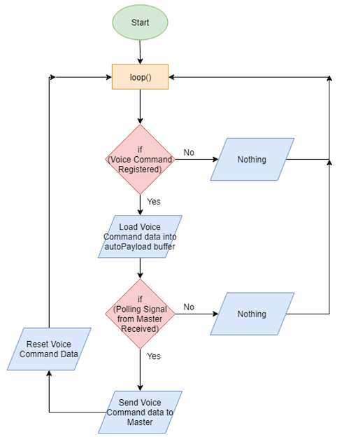
The flowchart for the operation of the master wireless communication system is as follows:
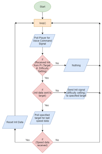
The flowchart for the operation of the player (slave) wireless communication system is as follows:
Module 6 Voice Control/Wearable Device
Player and device interaction will utilize voice recognition features and a touch screen interface on the launcher. This software is known to be reliable, has shown positive results when tested and allows the voice recognition system on S.T.A.R.S. to achieve a final success rate for processing voice commands at an acceptable rate. This task is made easier through the use of keyword recognition, as opposed to more general recognition. This will include an activation word and preset command phrases for which the system is trained on. The communication between the wearable microphone and launcher will likely result in some lag, meaning the collective system should be able to display a speech to text output on the touchscreen interface within a 5 second period of the user issuing a command.
Voice activation and a user interface represent vital components in the STARS launcher system, as this will be the sole form of communication through which the player may control the device, instructing it on what and how to run. In broad terms, there are 4 main routes through which computers may perform voice recognition: simple pattern matching, which seeks to recognize individual words entirely; pattern and feature analysis, recognizing words via their key parts (e.g. vowels); language modeling and statistical analysis, where knowledge of grammar and word use allows for predictability to increase accuracy and speed; and artificial neural networks, which mimic a human brain to reliably recognize patterns in words and sounds after significant training.
Generally, some combination of the second and third methods is used to build a reliable and accurate software, while minimizing the design and training requirements. Over time, these programs have evolved with varying levels of success to give modern voice recognition software a tall set of shoulders to stand on, yielding a standard for accepted levels of function. For these reasons, it is unreasonable to consider designing this software from scratch. Not being a crucial part of the engineering design for the final concept of the system, the creation of voice recognition software would very likely not be completed within the scope of this project to the same success rate as existing products. Instead, this module of STARS has been adopted from existing solutions, each of which were found to integrate well with the overall system and best suite the desired purpose.
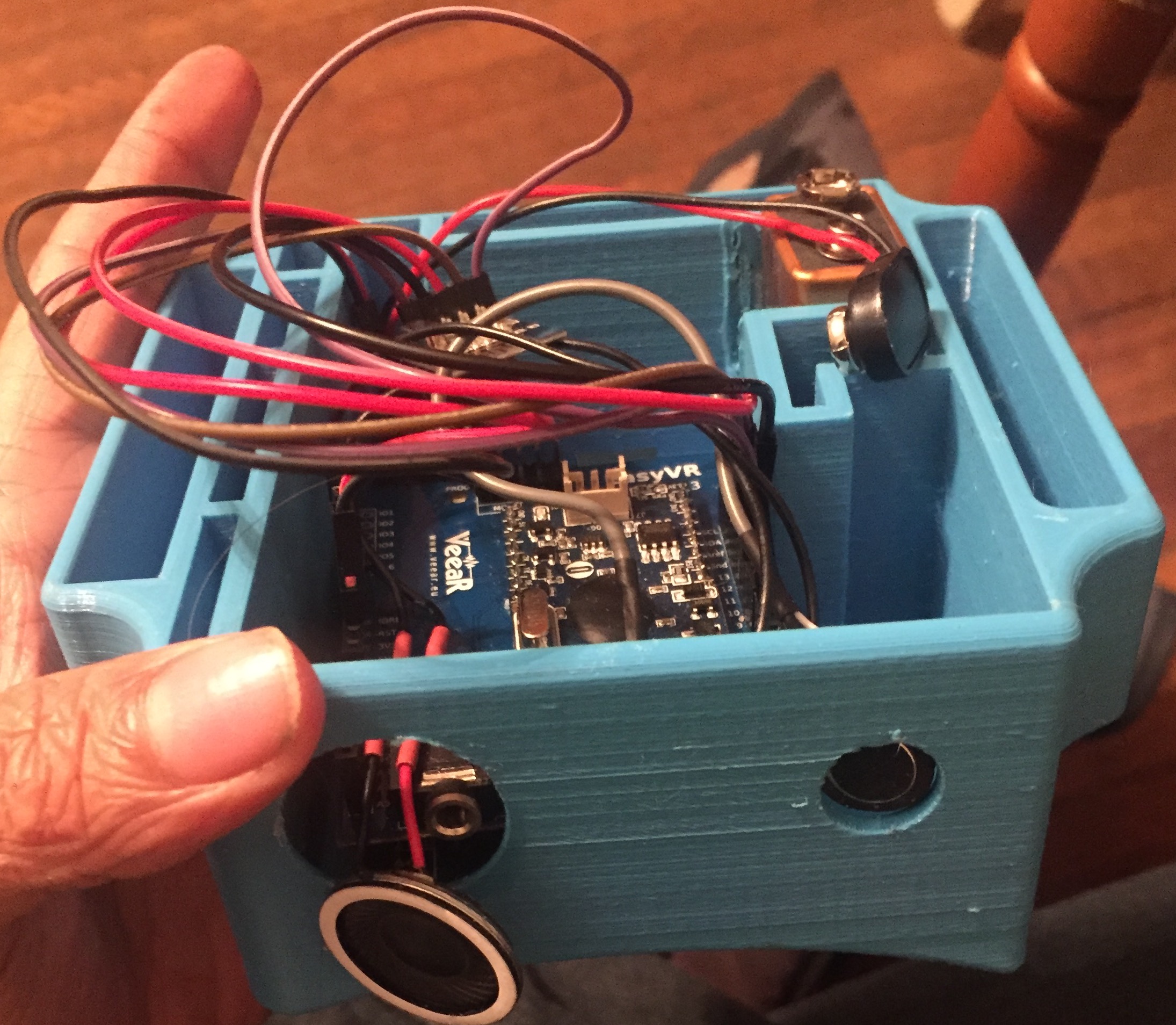
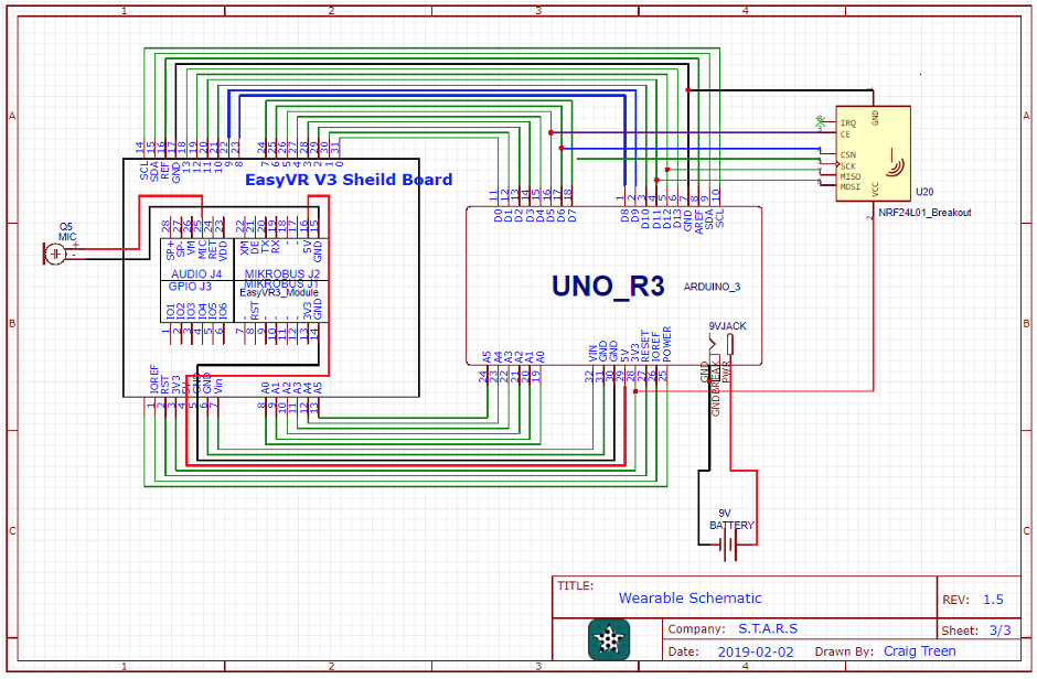
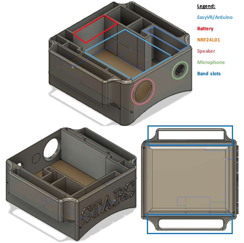
The main application of voice recognition in STARS is the integration of voice commands into the player’s wearable: in this case, Arduino-based modules are considered a simple, small and cheap method to provide reliable voice recognition to the player. This left the task of making a parts-based decision regarding an assortment of VR modules for the wearable. The EasyVR was instead chosen: the cost exceeded a few other devices. The deciding factor was the ability of the EasyVR to use both 22 preset commands, as well as include up to 32 trained custom voice commands (and a selectable trigger word). Assembled, the shield shares equal dimensions to the Arduino Uno and may easily fit on a wearable such as an athletic wristband.
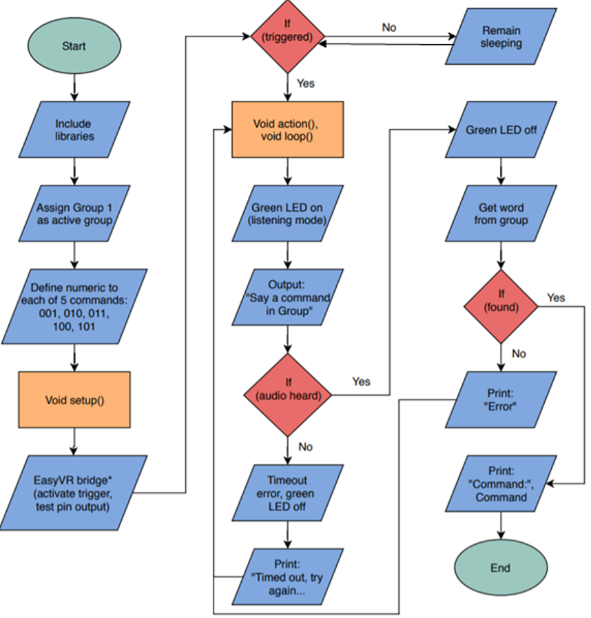
The EasyVR shield utilized only 4 pins on the Arduino Uno: Voltage source (3.3-5V), ground, TX and RX. Once mounted and connected to a computer, the shield could easily be programmed and trained using the recommended EasyVR Commander software. On this GUI, up to 20 groups may be used to store personalized commands (maximum of 32 per group) which may be named and trained by the user; however, only a single group of commands may be loaded onto the shield at a single time. When programming, creating and training the commands, the shield requires a group to be selected and uploaded onto the Arduino. This is done through the generation of a custom code by the EasyVR Commander support program which defines all user groups for the shield and indicates which is going to be used. Trained voice commands are stored on the shield’s module itself, though they are defined and accessed through the custom code. Before this code can be used, it must be edited by the user in several places to indicate specific parameters such as trigger functions, bridge connection, output (speaker) connections etc., as well as to define the actions performed by each command. The final code is of the form:
Module 7 Player Targets
Targets would be placed around the player, typically in a half moon configuration, these small nets are equipped with break-beam sensors for goal detection. Corresponding red, blue, and green LEDs are used to indicate inactivity, initialization, and successful goal detection respectively. Detection accuracy of this system is 100% due to where the sensors have been placed with the capability of detecting ball speeds up to 15 m/s.
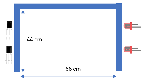
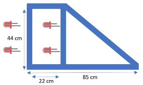
The targets consist of a durable, easily machinable ABS frame of dimensions shown below. They have two planes of break beam sensors, with each plane having a break beam sensor at ⅓ and ⅔ of the way up the frame vertically. This ensures that the ball will always break at least one of the sensors given its size of 22 cm in diameter. The two planes are used to ensure that a ball actually passes into the net and fully crosses the goal line, and that an accidental breaking of one beam will not falsely trigger a goal event. The separation of the two planes was designed to be the same as the diameter of the ball (22 cm) to ensure that the ball is detected in the instant that it fully crosses the goal line.
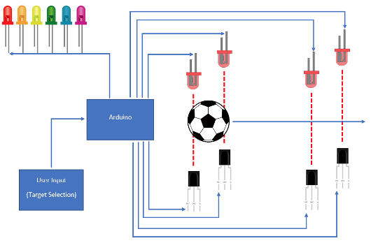
Each break beam sensor consists of an IR LED modulated at 38 kHz and a receiver tuned to that frequency so as to eliminate interference of DC IR light, which can be considerable in an outdoor environment. The central program determines which target should be activated, at which point it sends a signal wirelessly to that target and the LED strips mounted to the front of the target go from red to blue, signifying that the target is activated and ready to receive a ball. If the ball successfully crosses through both break beam planes, then the LED strip goes green, otherwise, the target waits for a certain period of time (determined by the difficulty setting chosen for the drill - less time for higher difficulty drills and vice versa) before the LEDs go back to red and the target waits for another input from the main program. The break beam sensors determine the speed of the incoming ball by noting the time at which the ball crosses the first plane and the second plane, using the Arduino micros() function. Since the sensors are a fixed distance apart, the speed can be found by dividing the separation distance by the time interval.
Each target is powered by a 12V battery pack in order to ensure portability and provide the necessary 12V to power the LED strips. A 12V to 5V regulator module is included to provide power for the Arduino Nano, the break beam sensors, and the nRF24l01 wireless communication module.
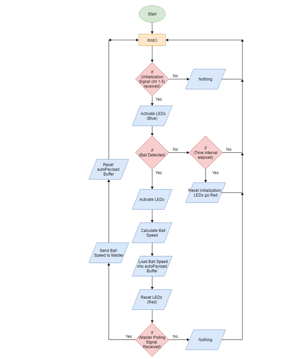
A flowchart demonstrating the functionality of each target is shown below:
Module 8 Graphical User Interface
The screen itself will have a main menu for the user to select from a variety of drills. Each drill will possess a submenu for controlling parameters such as ball speed or pass type.
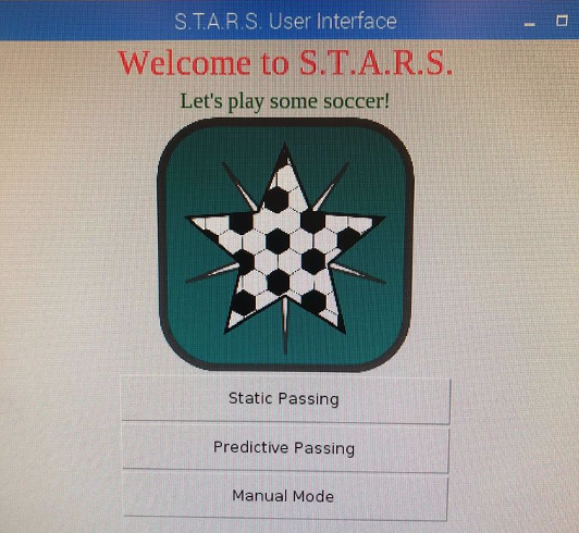
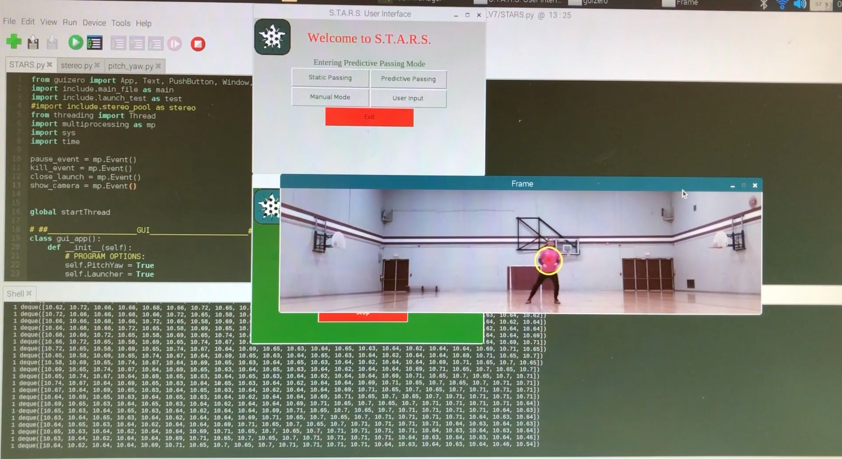
The touchscreen user interface utilizes Pythons GUIZero and Tkinter modules for a straightforward, programmer-friendly design of a standard GUI. The code includes widgets such as Apps, Text, Pushbuttons, Images, Sliders and additional Windows. The underlying map of the GUI provides a straightforward main menu, welcoming users and offering them a choice of 3 drills: Static Passing, Predictive Passing or Manual Mode.
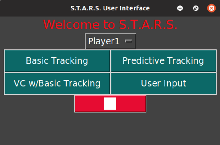
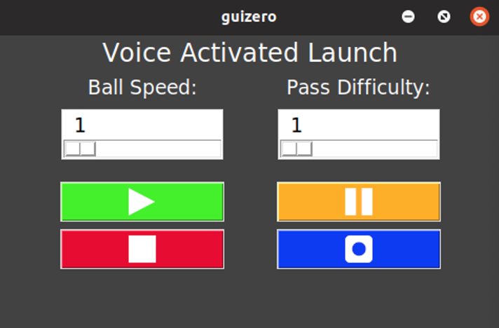
Prior to drill selection, the user selects a player name from the drop down list, and a new window is opened to display the drill parameters for the players selection. These parameters can include start/pause functions, ball speed and number of targets. The below submenu as well as selection actions demonstrate the touch screen functionality.
Though the screen is very responsive to touch and maintains a locations accuracy of <0.5cm, a stylus is included for ease of use due to the very small screen size, allowing for usage without blocking of the screen from the users own hand.
Module 9 Central Control System
The main focus and challenge of integrating the device, is the overall control system. Since the stereoscopic system requires two Raspberry Pi’s, it is necessary to include the remainder of the systems control onto the Raspberry Pi acting as a server. The reason for this is largely due to the lack of inbuilt Pi to Pi communication making way for us to use the ethernet communication port (using TCP/IP protocol) the easiest method to accomplish this goal. However, each device only has one port. Further complicating the task of control is the need to perform several continuous loops at the same time. The Python language provides many different methods/modules to do this, some of which are: multithreading, multiprocessing, and simply using the import function to add more files. Importing modules and running as processes however, limits the means by which they can share data, while the multiprocessing method is intended for more memory intensive processes. The Python multithreading module allows for multiple tasks to be performed at the same time, while still within the same process and hence the same memory space, allowing the created threads to easily share data.
Though identical in syntax, python processes have certain advantages over threads, specifically when these objects are running tasks that already take advantage of multiple cores, such as basic math and data processing. For example, running mulitple threads that are leveraging the multicore CPU will cause these threads to simply run one after another, but if the task is single core, for example the image processing using the OpenCV library has many single core functions, and so threading the camera processing with a pool of workers would make a lot of sense. As the size and scale of the individual functions has increased: Pitch and Yaw control, Launcher control, and Stereoscopics - running them as threads introduced many anomalies in timing and data output. After changing the syntax to start these functions/class-objects as processes (using the multiprocessing library), the timing issues were largely resolved.
Since the program uses a combination of processes and threads, some distinction is made between how they each communicate. As mentioned, processes reside in a separate memory space and share nothing with the other process to avoid corruption of data, as result, inputting and outputting data between processes has some caveats. Included in the multiprocessing library are several process safe methods of communication (Queues, Pipes, and Array & Value), the simplest of which is the multiprocessing.Queue() object, chosen for its ease of implementation. Queues from the multiprocessing library differ from those provided in the threading module, for example, they only support a first-in-first-out (FIFO) data structure, and dont allow some of the extra options that are provided in threads (appendleft(), popright(), etc…). This makes passing time sensitive data more complicated, requiring that the current data point is added to the Queue by the producer, only when the consumer is requesting it, this is done by using the Event object provided in multiprocessing.
Communication between threads however is significantly simpler, allowing more complex objects to be passed using Stacks(). Stacks in Python allow for greater flexibility inherent to the data structure. For example, multiple threads and functions can access the same data simultaneously using the peek function, while leaving the data available for later use.
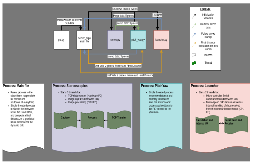
The program structure shown below includes one Python script for the graphical user interface (GUI), and four module files instantiated as processes, which also include several threads. The stereoscopic process simply repeats its image acquisition and comparison loop (~5-8 frames per second) so as not to slow down this critical function the values it detects are pushed to the Pitch and Yaw motor thread, and these two work incongruously to keep the launcher directed at the player at all times. Distance data from the launcher thread. The chaotic appearance of the data flow is largely a result of the availability of serial ports on the Raspberry Pi, since a serial port may not be read asynchronously by two different calls, or even be open in two different data streams. Furthermore, the timing and memory limitations of the Arduino microcontrollers limit where each physical component of the device can be input to the Raspberry Pi.
In addition to the plethora of data I/O within the program shown, analysis and correction of the data is also very important for the values being fed to the motors, many failsafes and proper shutdown procedures are important. For this reson, shutdown and locking events are implemented using the Event() object from the multiprocessing library. In order to further increase safety and prevent anomalous distance readings from sending large values to the motors when the distance tracking is reading a closer distance most of the time, data smoothing has been implemented using a running averages convolution. Using a small window of five past data points with a kernel size of three, using the Python 3 numpy module which includes a convolution method np.convolve three running averages. From this data, a direction and rate of data change is inferred by taking an average of differences from the past threes means. In doing so, the future data may be naively anticipated in order to sicount anomalous distance readings.
Given the limited processing power of the Raspberry Pi 3B + model, it is required that much of the programming methods be implemented in an efficient manner, making use of object oriented programming methods.
System Design and Engineering Drawings
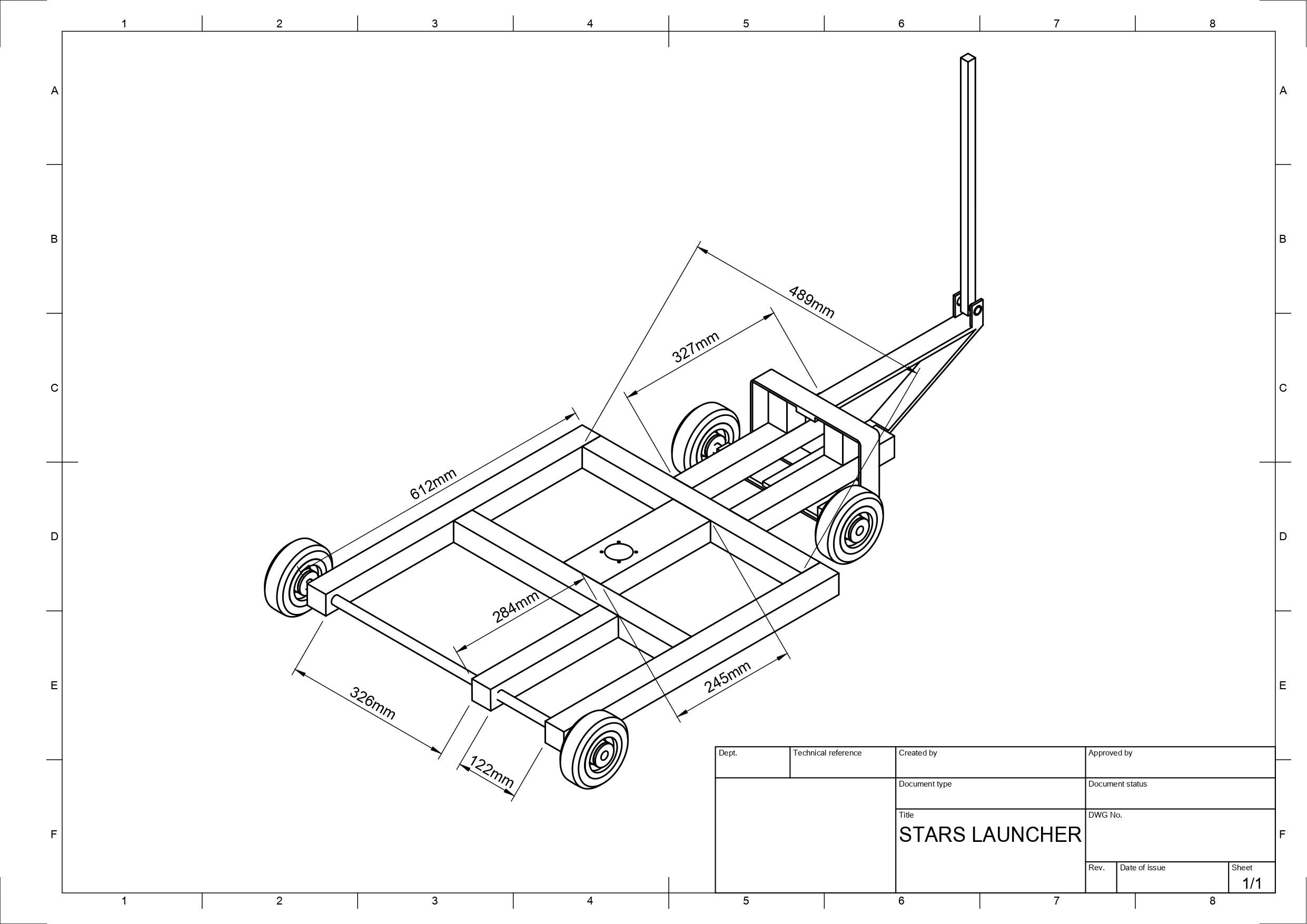
Fabrication of a large physical machine of a scale to launch soccer balls requires some significant planning and fabrication work. Without access to any metal fabrication facilities, the ability to produce unique parts for the purposes of a prototype are usually not possible, and modelling or CAD design impractical. Utilizing available materials, a cart was constructed to act as the base and provide mobility to the device in addition to vibration dampening for hard gym floors.
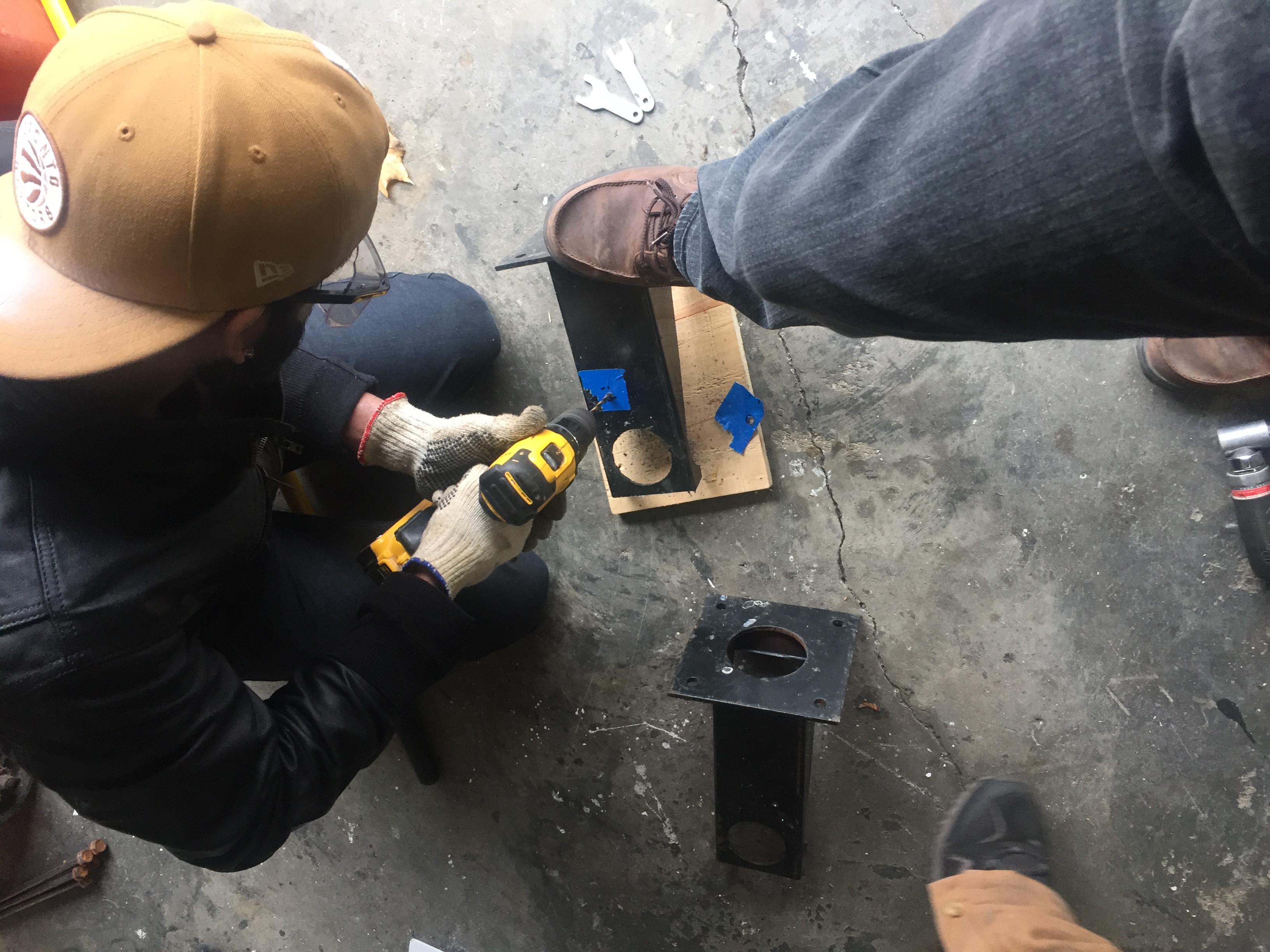
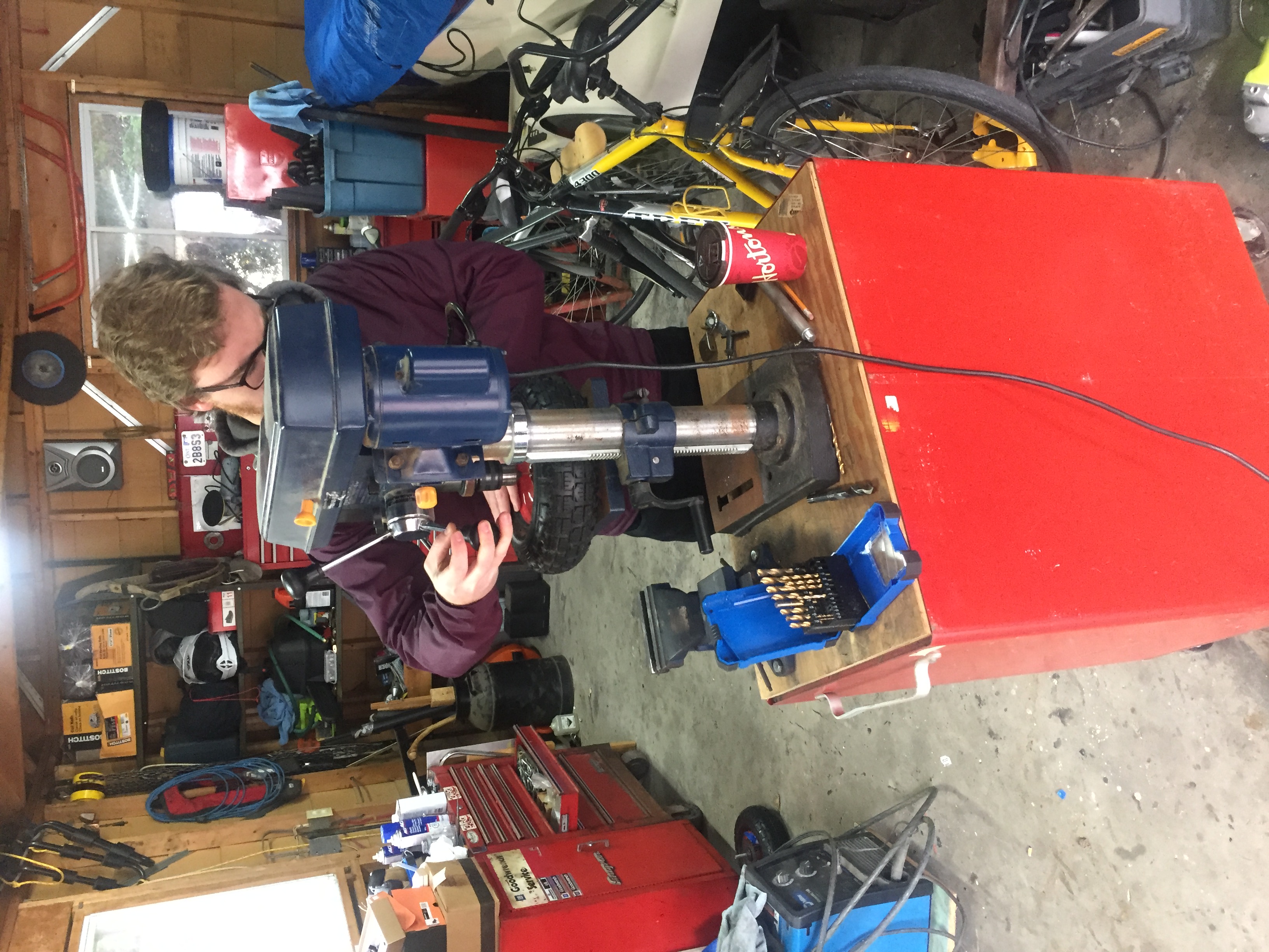
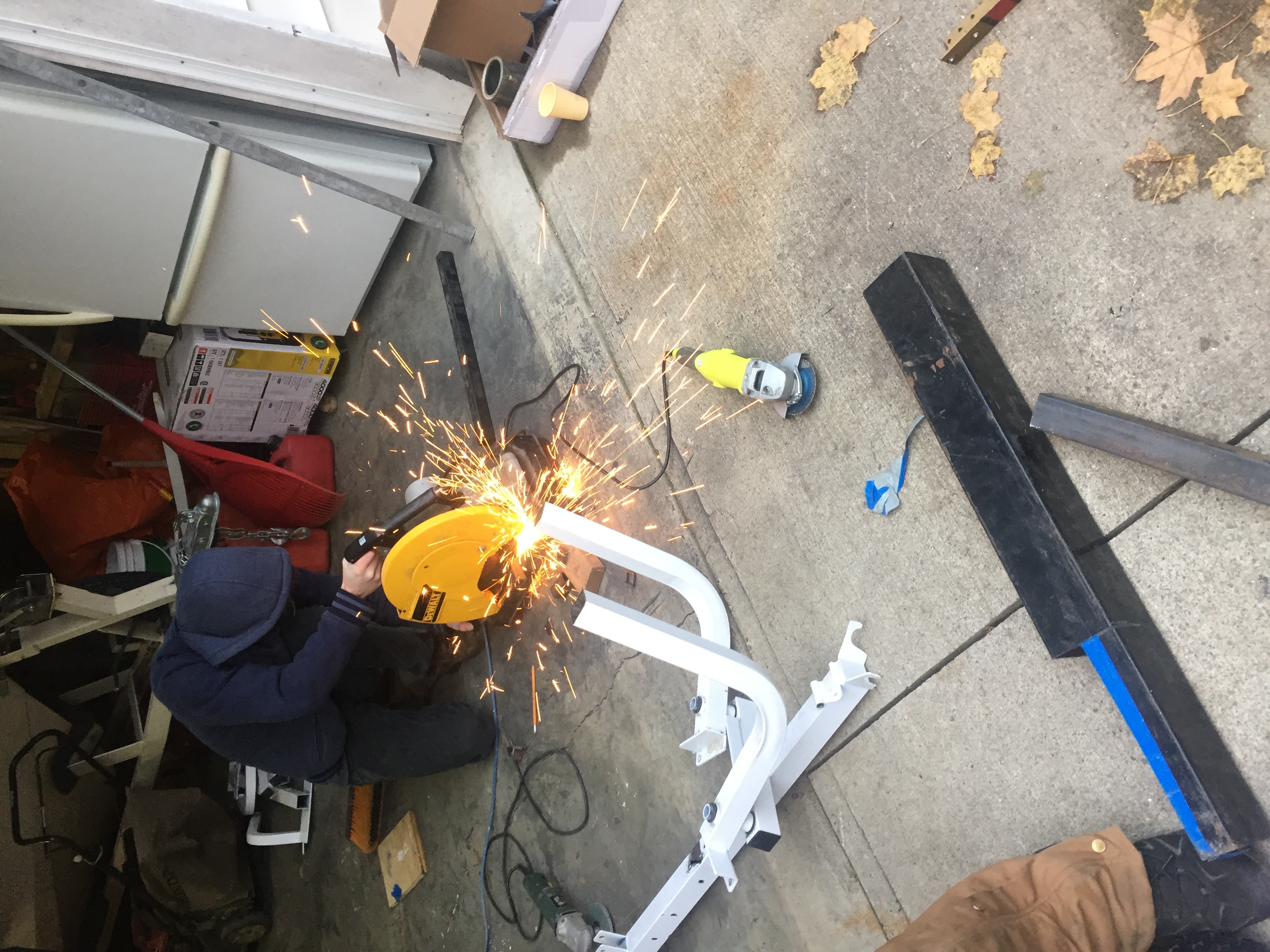
Fabrication of a large prototype typically can be done from blueprint or rough sketch, the actual constraints of the machine are relatively simple given the compromise of motors, time and budget. Designing a chain driven launcher wheel would be the ideal solution for a cheaper motor, but the fabrication cost does not justify the trade-offs. Since the wheel needs to be driven directly off the motor shaft for this reason, limiting the possible size of the wheels to something ~10 inches in diameter due to higher weights increasing the torsion on the shaft as well as increasing angular momentum and inertia.
Concerns of the stresses to the motor shaft led to several design choices, namely having the rotational axis point in the upright direction to negate the effects of gravity on the balance of the wheel. A secondary purpose of this design is to manipulate the curvature of the ball left or right. On top of the shear stress experienced by the shaft, the launch itself causes a significant reactionary force (linear torque) as the ball is pushed through the two wheels. This force at launch required some mobility to launching motor mounts to absorb some of the shack from the launch.
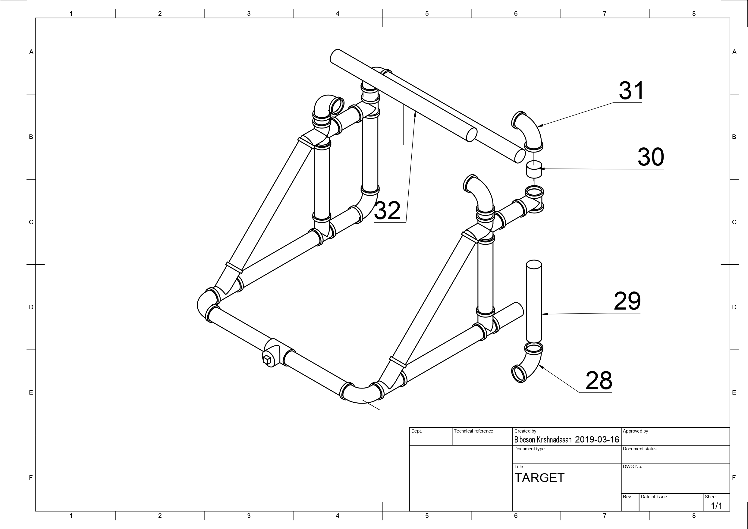
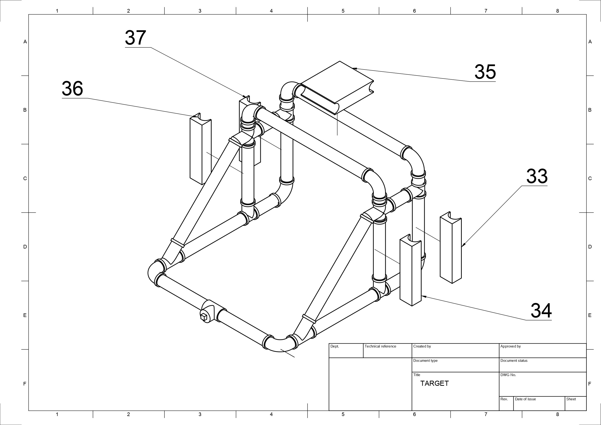
STARS BALL LAUNCHER
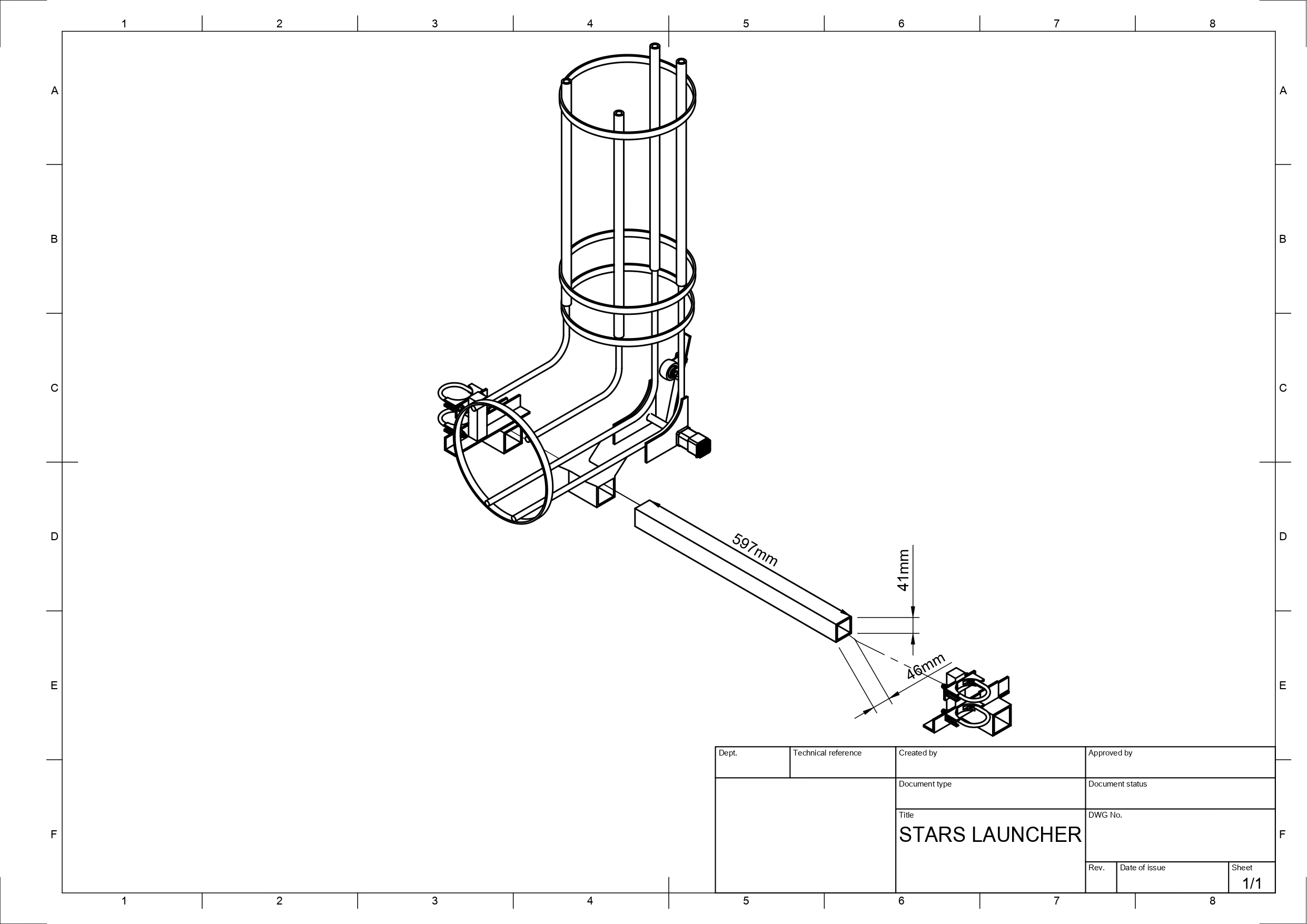
Chassis
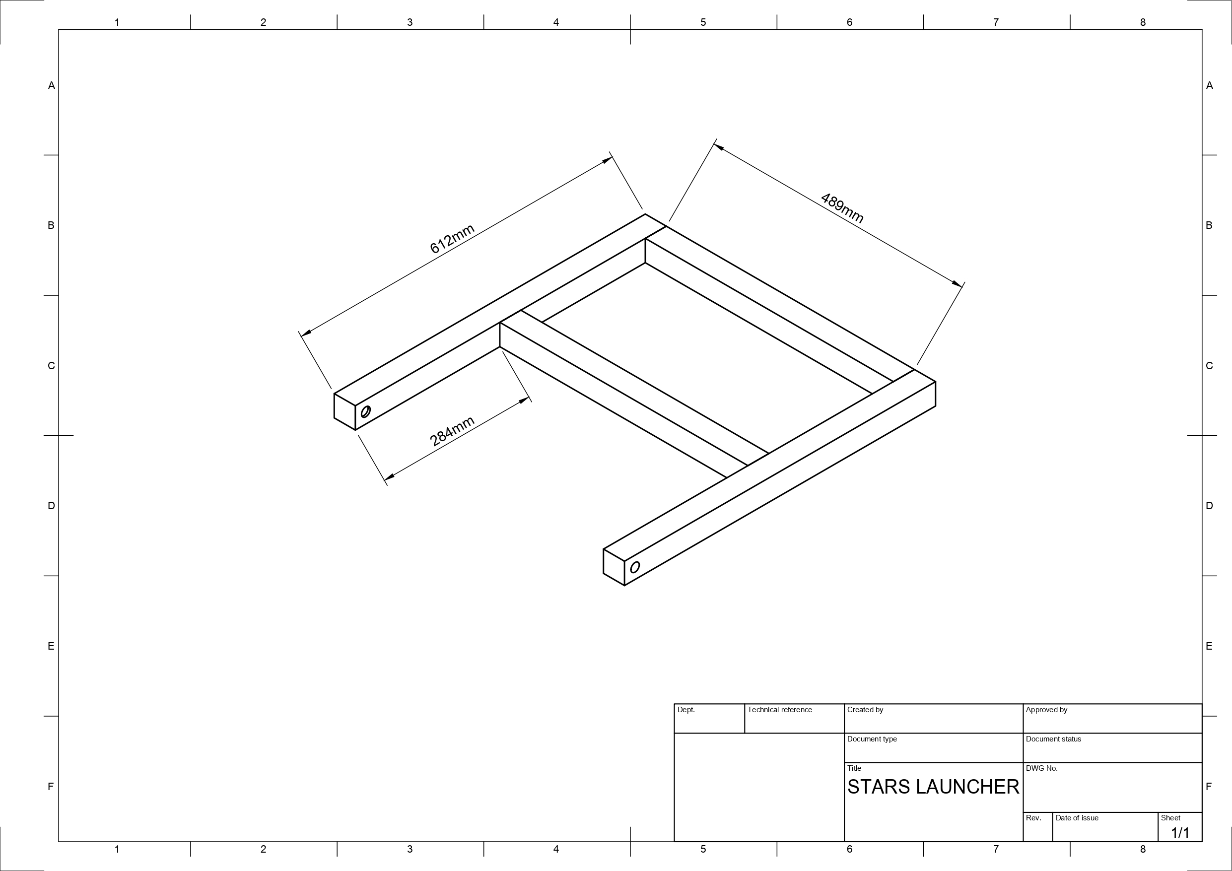
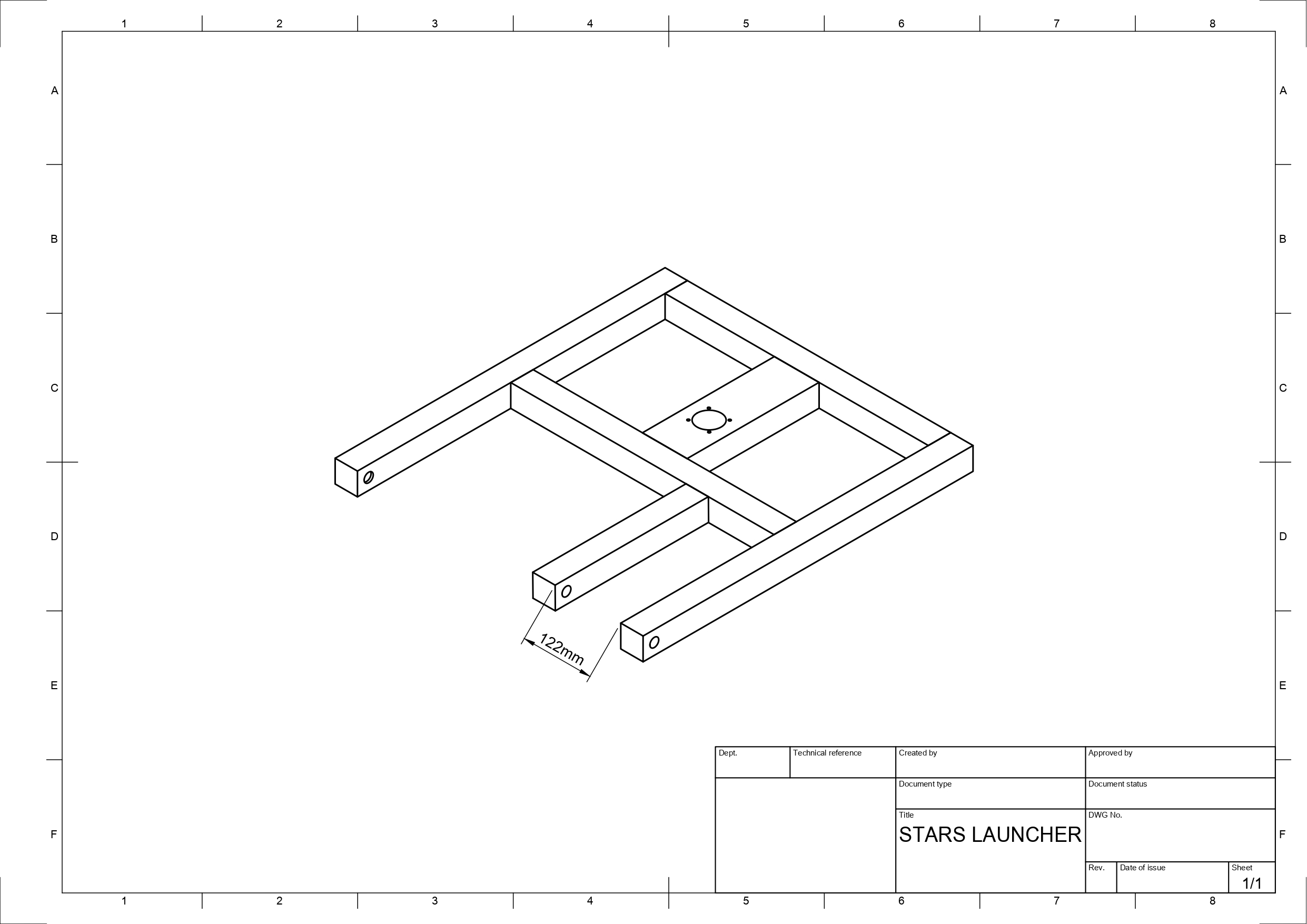
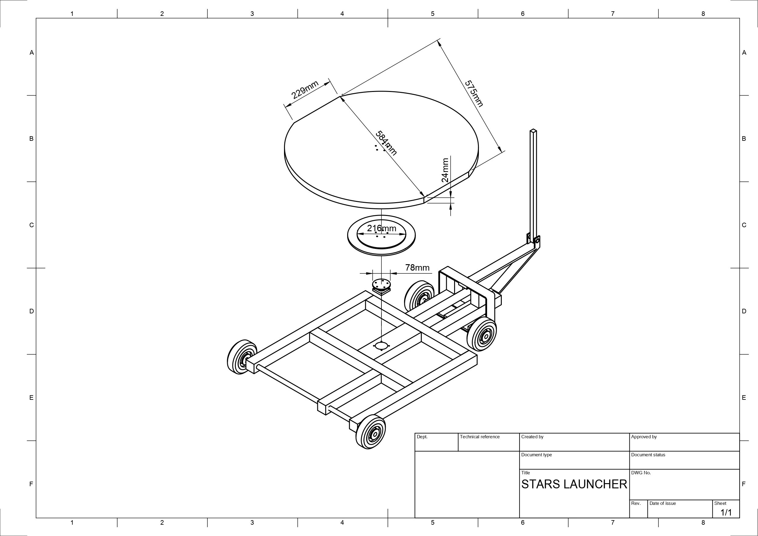
Platform
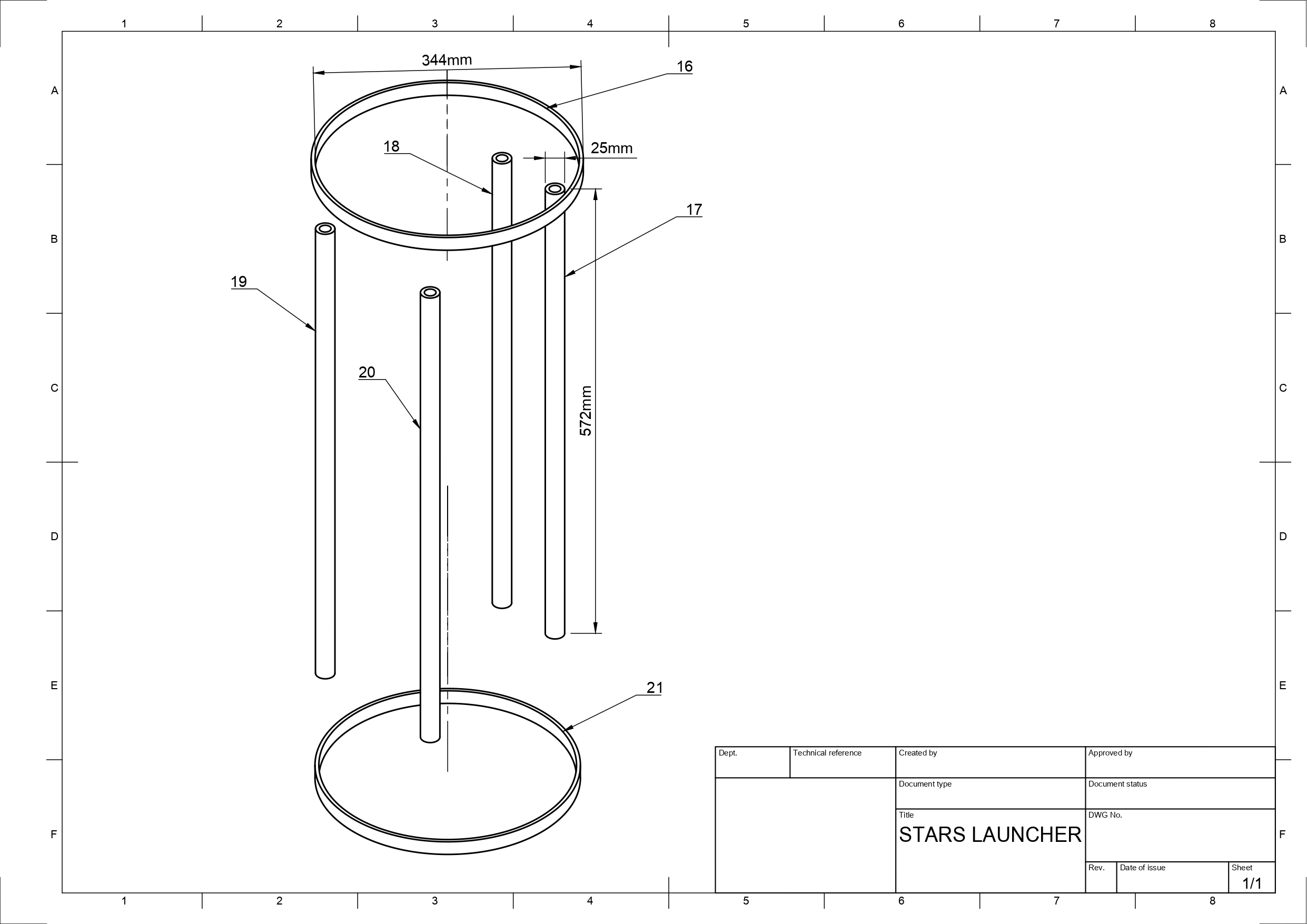
Launcher Motor Supports
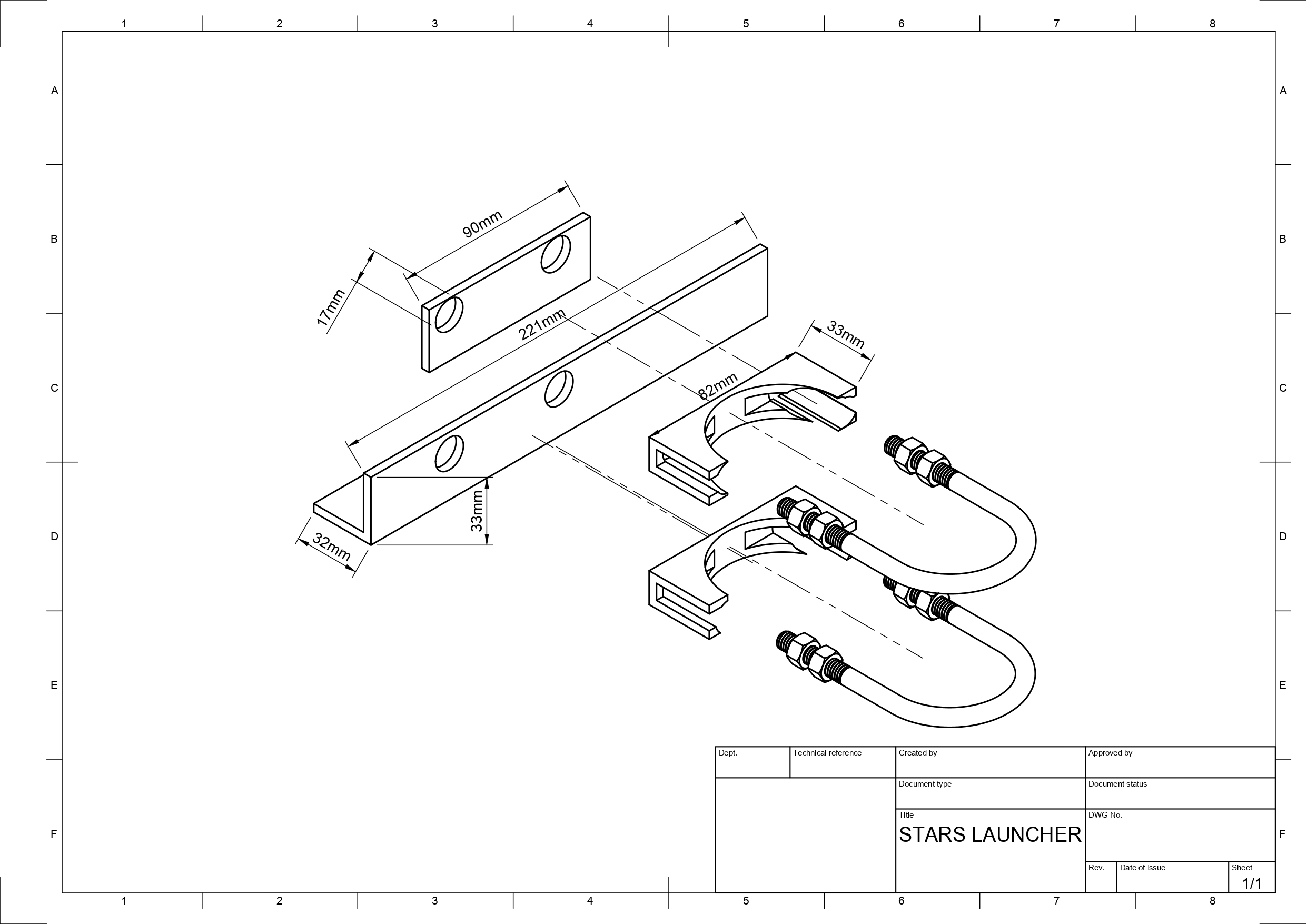
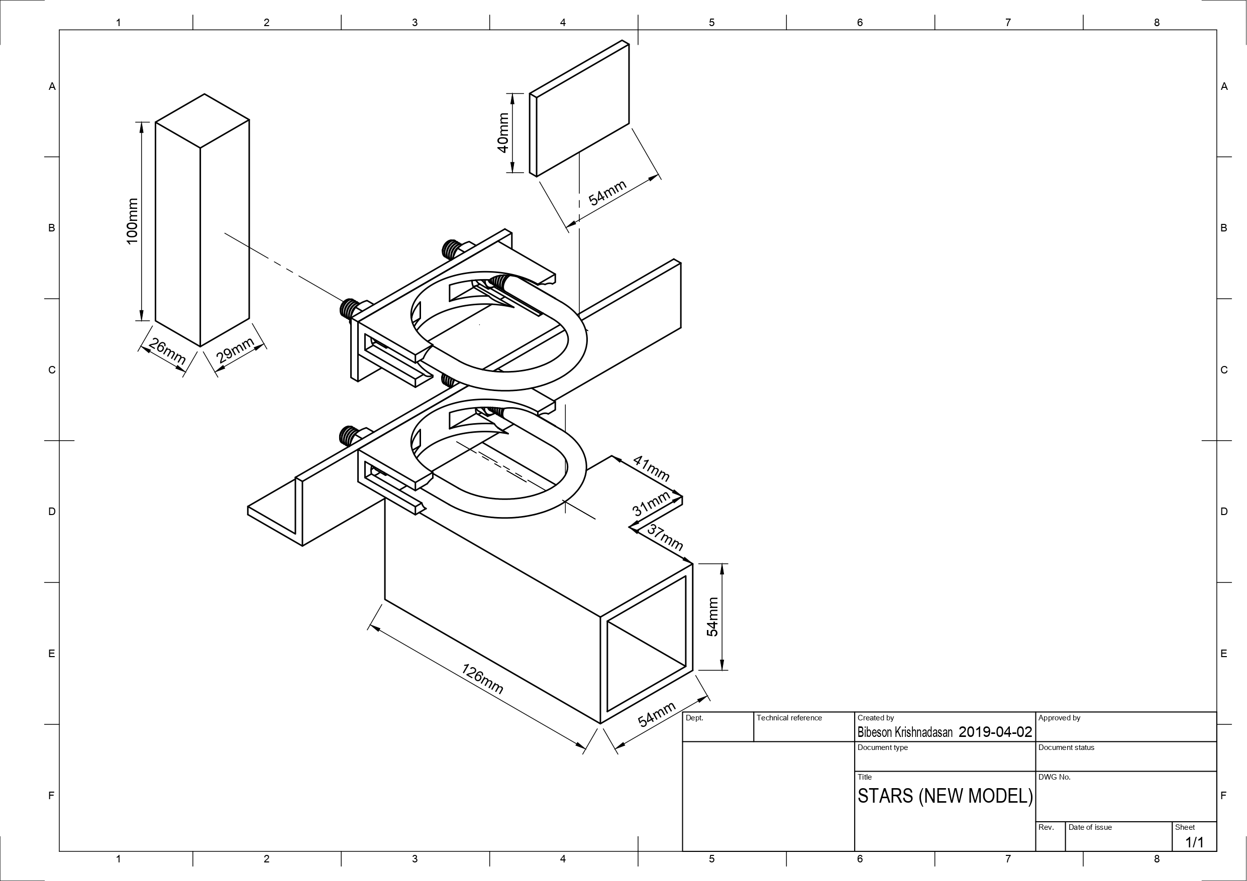
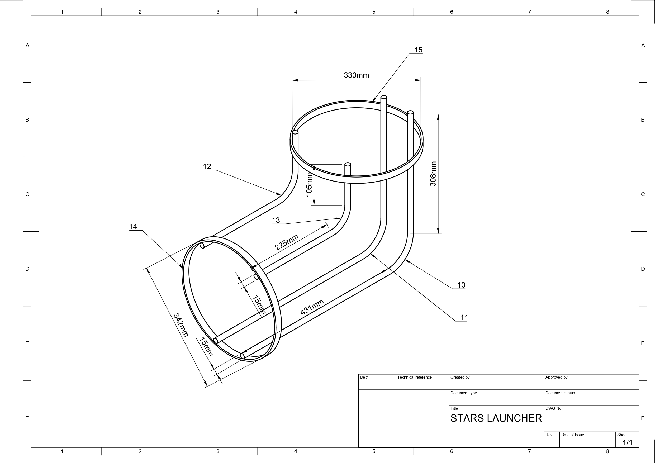
Launcher Bar Support
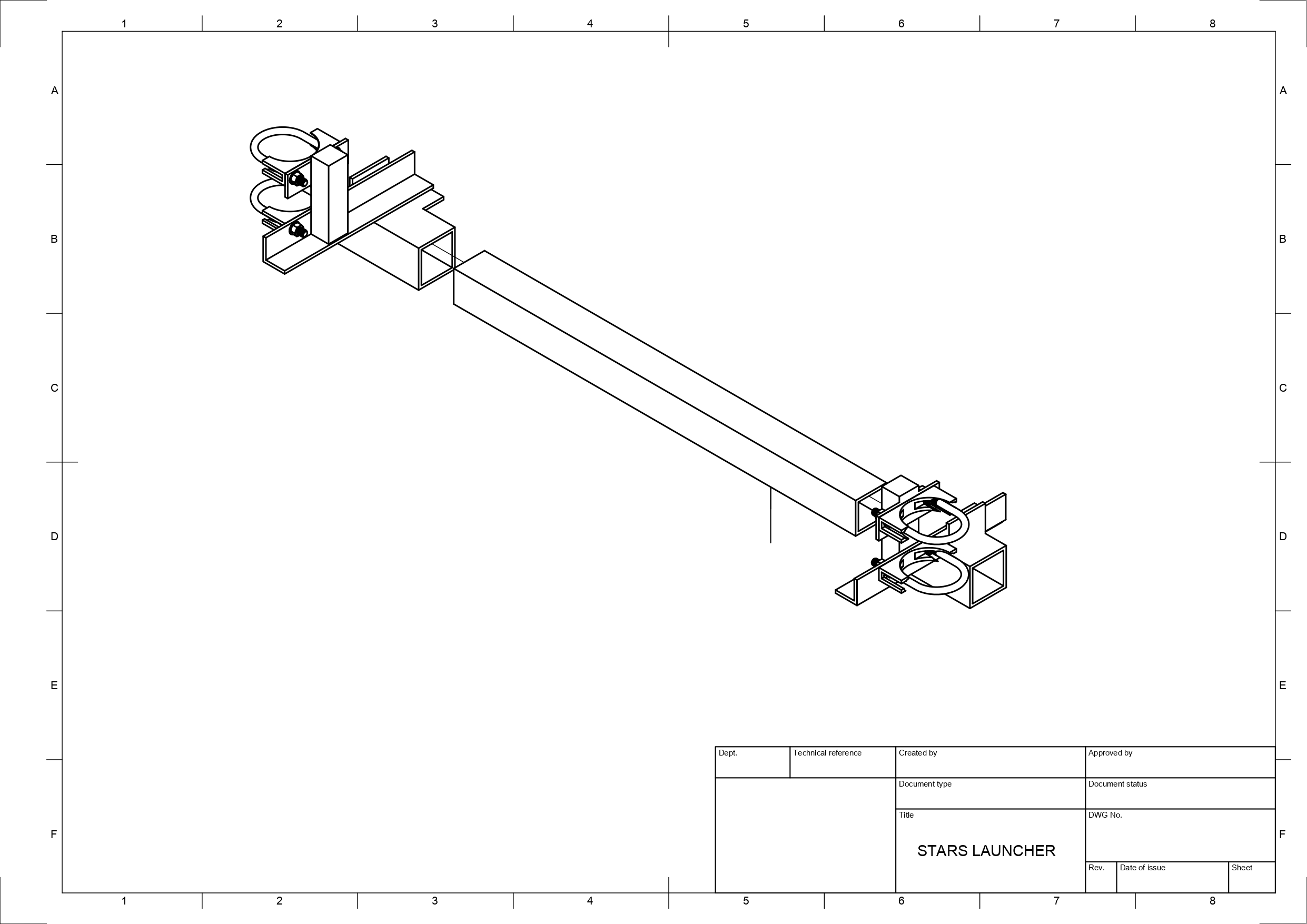
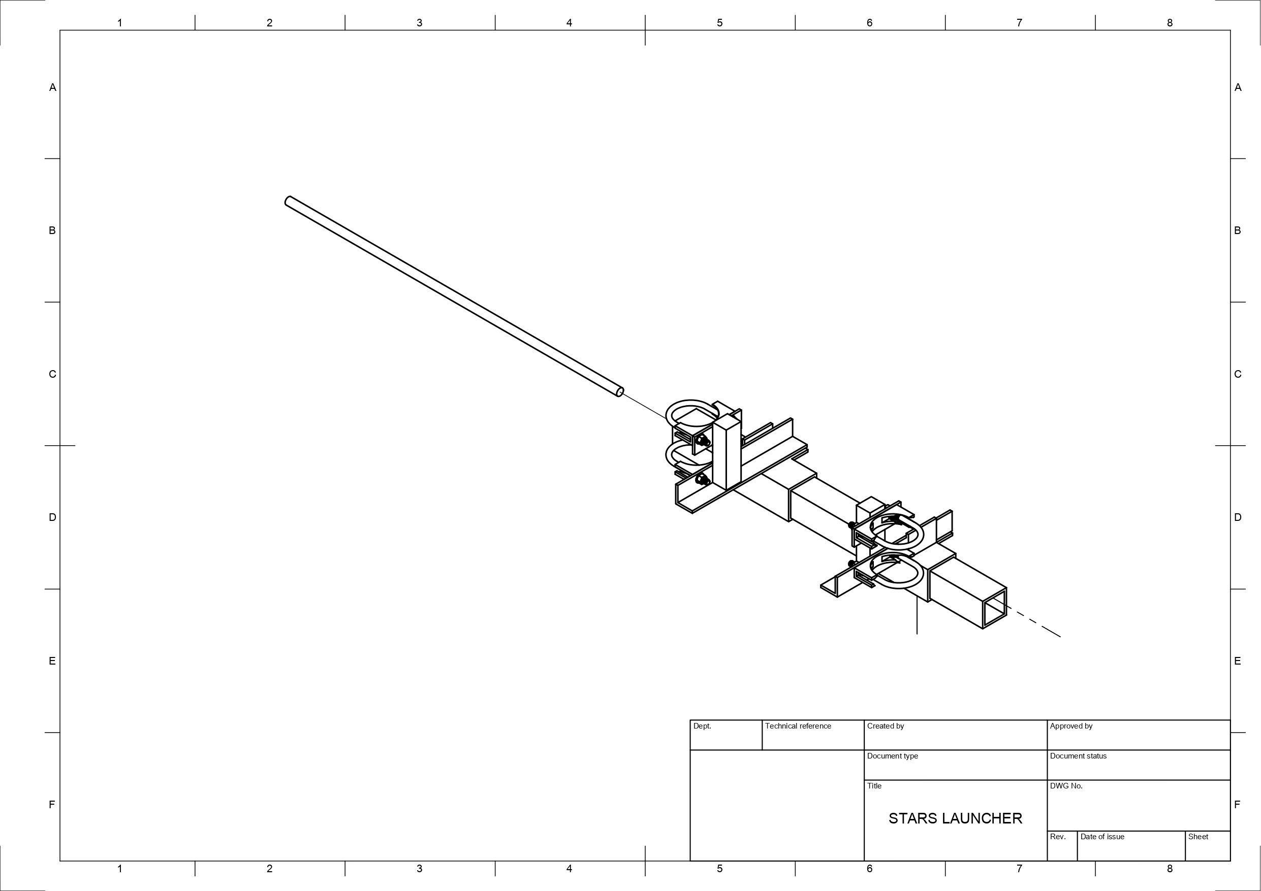
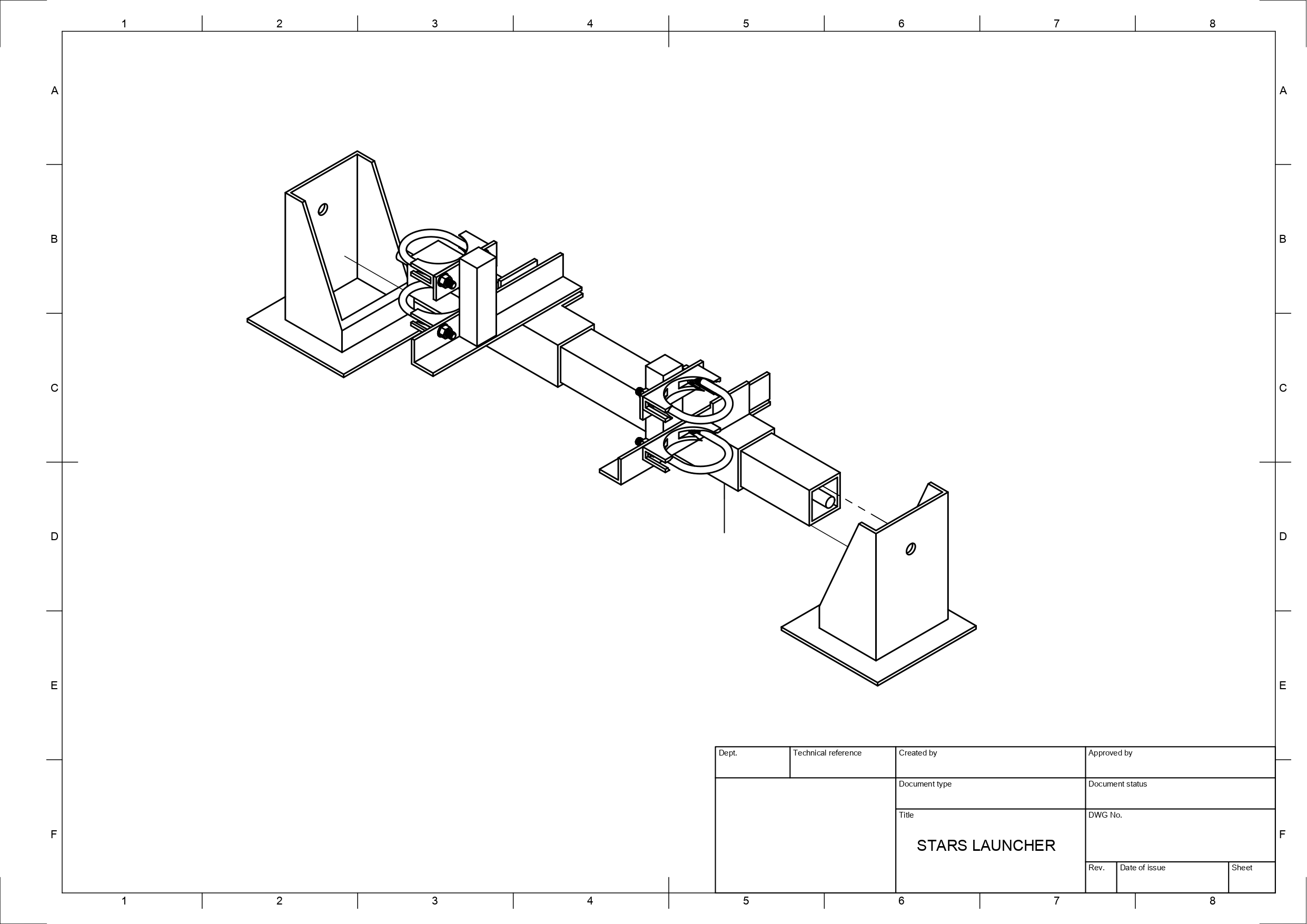
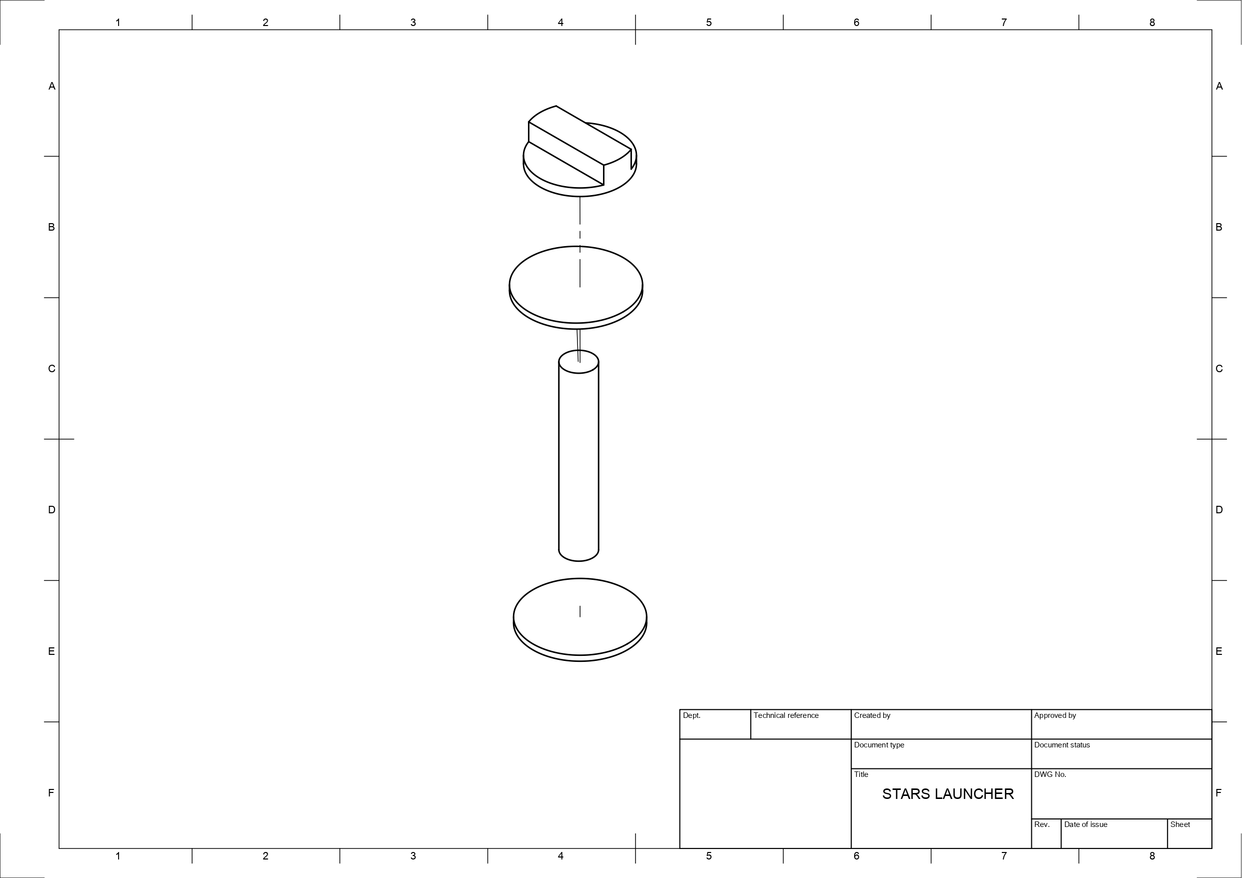
Ball Feeder
Stereoscopics
Targets
Power Management
The launcher and all modules mounted on the platform should be powered exclusively by the vehicle batteries. The two batteries, when placed in series, provide the launcher with +24 V, which requires voltage regulation to step down this voltage to power other motors and electronics mounted on the platform. Two voltage regulator circuits, outputting +5 V and +12 V respectively, were designed and developed for this purpose. +5 V is required for powering the Raspberry Pis, and +12 V is needed for powering the pitch, yaw, and ball feeder motors, the Arduinos (via the +12 V to +5 V regulator mounted on the H bridges), and the cooling fans. Due to the large steps down in voltage required for each rail, switching regulators were chosen over linear regulators as the latter would dissipate too much heat and be too inefficient to maintain a stable output voltage at all times. The TPS54560 integrated circuit from Texas Instruments was chosen for this application, as it has a large range of input voltages, has a wide operating temperature range, has a relatively small PCB footprint, and can output up to 5 A. The following circuits were designed based on the suggested circuit listed in the datasheet:
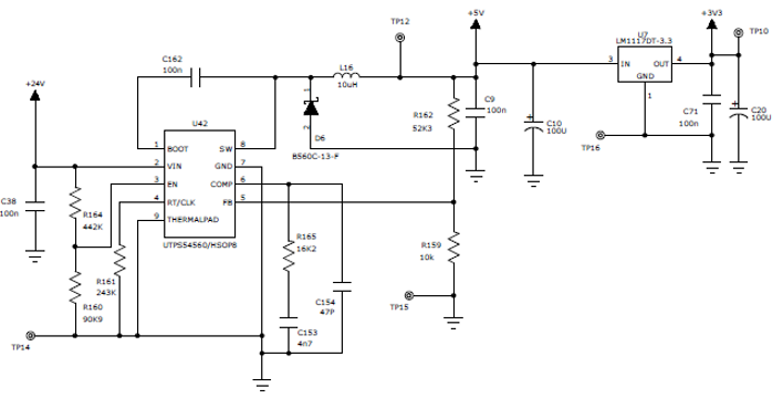
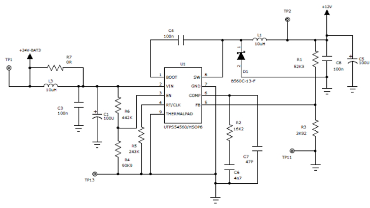
These circuits are very similar to each other. The feedback pin (pin 5 on the TPS54560 chip) has an internal reference voltage set to +0.8 V, which in turn controls the output voltage via the voltage divider applied over this pin. Using the Webench simulation tool provided by Texas Instruments, both circuits were modelled and analyzed as shown below.